Ammonia method desulfurizing method and device

An ammonia desulfurization and desulfurization tower technology is applied in the field of ammonia desulfurization, which can solve the problems of unsuitability for large flue gas volume, uneconomical, and excessive ammonia release.

Inactive Publication Date: 2007-10-17
中国自控系统工程有限公司
View PDF2 Cites 10 Cited by
  • Summary
  • Abstract
  • Description
  • Claims
  • Application Information

AI Technical Summary

Problems solved by technology

Ammonia desulfurization has attracted much attention due to its high efficiency, desulfurization by-products are chemical fertilizers, small footprint, and small investment. Causes secondary pollution to the environment, so it is subject to some restrictions in marketing
[0003] At present, most of the desulfurization towers in the ammonia desulfurization process mainly adopt the absorption liquid spray absorption method, which will mainly cause a large amount of ammonia escape in the outlet flue gas, causing secondary pollution to the surrounding environment
[0004] There are also some desulfurization and desulfurization towers that use trays to absorb sulfides, but because the flue gas temperature is difficult to drop to the optimum temperature of 60 degrees for desulfurization when passing through the trays, the absorption liquid in the trays absorbs the sulfide in the flue gas After that, under high temperature conditions, it will be decomposed soon. Only by adding excessive ammonia to absorb the sulfide in the flue gas, this will cause a large amount of absorbent, which is uneconomical, and the amount of ammonia escape at the outlet is also large, and the outlet is decomposed. The sulfide and ammonia escape will continue to react, and the by-products will be attached to the outlet flue. The amount of by-products that can be collected is small, and the outlet flue is easy to block
[0005] There is also a form of spraying under the tray of the desulfurization tower, but this absorption method basically relies on tray absorption. In order to ensure the desulfurization rate, it is necessary to ensure the reaction time of the flue gas passing through the tray and the absorption liquid on the tray. Therefore The hole spacing of the tray design is small, the resistance is large, and the energy consumption is high. When the flue gas passes through the liquid film of the tray, the droplet entrainment is serious
[0006] Chinese patent 200310115523.2 provides an integrated ammonia-based desulfurization and dust removal tower. The desulfurization and dust removal tower is equipped with a primary spray section, a tray layer and a demister from bottom to top. The disadvantage of this device is that it is not suitable for dealing with heavy smoke gas volume, and when the tower diameter of the desulfurization tower is large, the solution on the tray plate is difficult to distribute evenly
However, due to the use of oxidation treatment in the tower, this process and device will affect the desulfurization rate of the entire desulfurization system. If in order to ensure the desulfurization rate, excessive ammonia gas is added for absorption, and the ammonia escape in the outlet flue gas will inevitably exceed the standard.

Method used


Image

  • Ammonia method desulfurizing method and device

Examples


Embodiment 1

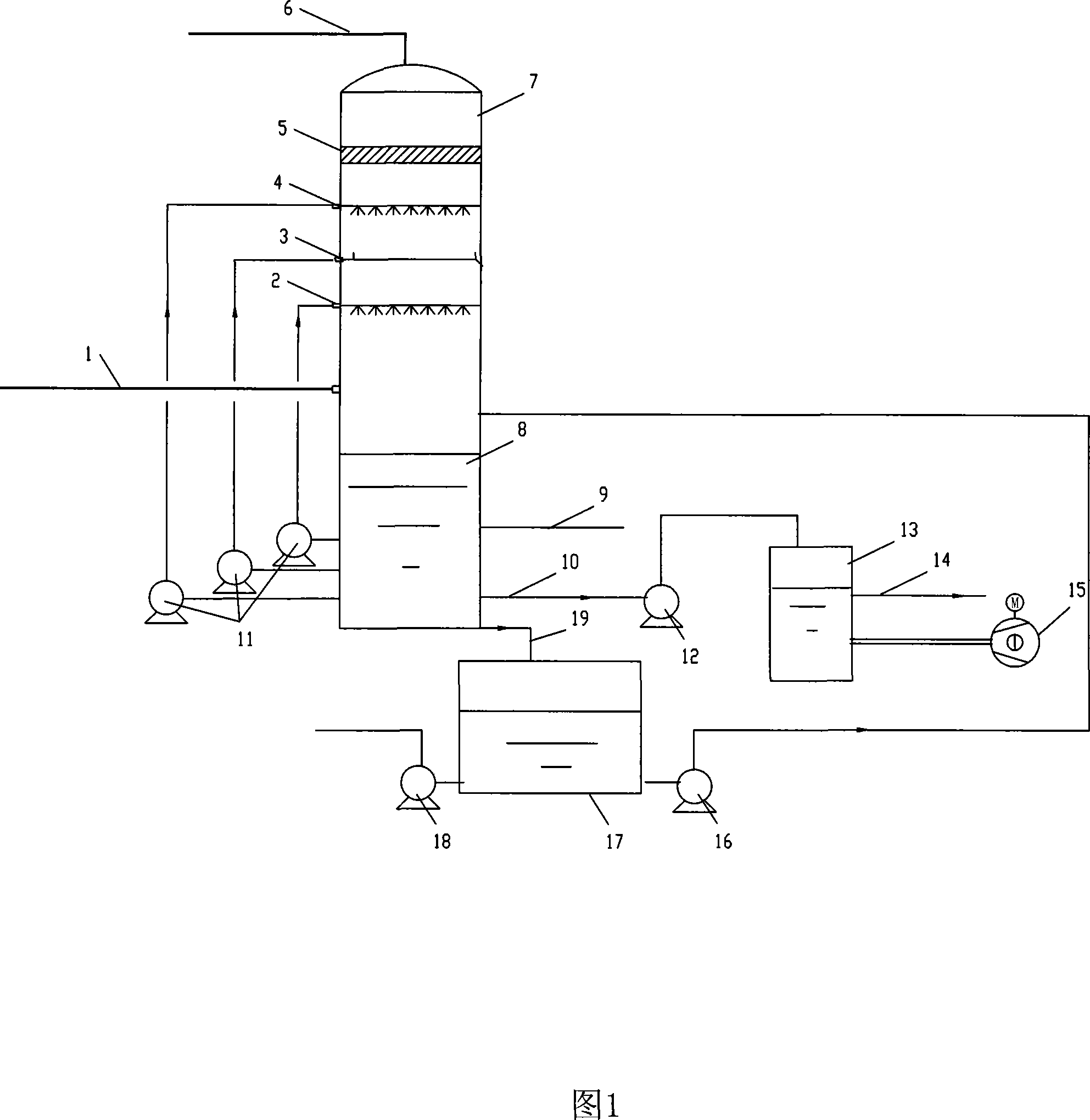
[0050] A desulfurization tower 7, including a solution pool 8 at the bottom of the desulfurization tower, a primary spray section 2, a tray layer 3, and a secondary spray section 4 from bottom to top, wherein the primary spray section 2 includes 1-3 layers of spray The shower device, the tray layer 3 includes 1-2 trays, and the demister 5 is installed above the secondary spray section 4, which is connected with the flue gas outlet 6 at the top of the desulfurization tower; the primary spray section in the middle of the desulfurization tower 2 is provided with a flue gas inlet 1 below; the side of the solution pool 8 at the bottom of the desulfurization tower is connected to the ammonia injection pipe 9; three circulation pumps 11 are arranged outside the tower, and the outlets of the above-mentioned circulation pumps 11 are respectively connected to the primary spray The shower section 2, the tray layer 3, and the secondary spray section 4 are connected, and the inlets of the c...

Embodiment 2

[0054] The rest is the same as that of Example 1, except that the flue gas inlet channel contains a cooling heat exchanger.

Embodiment 3

[0056] Flue gas from the boiler with a temperature of 120°C 1×10 4 The standard cubic meter per hour enters the desulfurization tower 7 from the flue gas inlet 1, and the sulfur oxides in the flue gas are 1600ppm. First, it is cooled to 65-70°C through the primary spray section 2, and part of the sulfide is absorbed, and then The flue gas passes through the tray layer containing 1 tray, and the liquid film flowing on the tray fully reacts with the flue gas when the flue gas passes through, removing most of the sulfides in the flue gas, and then the flue gas The gas continues to rise and then passes through the secondary spray section 4, absorbing a small amount of escape ammonia contained in the flue gas. The absorption liquid of the spray section and the tray layer is 30% ammonium salt solution, and finally ammonium sulfite is entrained. When the flue gas of liquid droplets passes through the demister 5 at the top of the tower, the ammonium sulfate droplets entrained in the f...


PUM


Abstract

The invention disclose a method of ammonium desulfurization and device thereof, and Specifically, the method of the invention utilizes a novel thionizer coupled with the ammonium salt oxidizing tank outer the thionizer to deprive the sulfur oxides and dust in the flue gas step by step via the manner of coupling the sprinkling section with the plate. Using the desulfurization method and device thereof said in the invention, the efficiency is high, the operating trouble is low, and the reconditioning is convenient. The invention also has the advantage of a low content of ammonium and ammiaonia sulfate aerosol, low dust in outgrowth and fine quality.

Description

technical field [0001] The invention belongs to the technical field of boiler tail gas treatment, in particular to a method and device for ammonia desulfurization. Background technique [0002] With the development of the economy, the progress of society and the enhancement of people's awareness of environmental protection, industrial flue gas removal of SO 2 increasingly received attention. Ammonia desulfurization has attracted much attention because of its high efficiency, desulfurization by-products are chemical fertilizers, small footprint, and small investment. It causes secondary pollution to the environment, so it is subject to some restrictions in marketing. [0003] At present, the desulfurization tower in most ammonia desulfurization processes mainly adopts the absorption liquid spray absorption method, which will mainly cause a large amount of ammonia escape in the outlet flue gas, causing secondary pollution to the surrounding environment. [0004] There are a...

Claims


Application Information

Patent Timeline
Patent Type & Authority Applications(China)
IPC IPC(8): B01D53/50C01C1/22
Inventor 赵焰
Owner 中国自控系统工程有限公司
Why Eureka
Try Eureka