Electrode for electrolysis and electrolysis unit

A technology for electrodes and surface layers, applied in electrolysis components, electrodes, electrolysis processes, etc., can solve problems such as increased device costs, low ozone generation efficiency, and more energy, and achieve production costs, environmental burdens, and power consumption volume effect

Inactive Publication Date: 2008-09-10
SANYO ELECTRIC CO LTD
View PDF4 Cites 0 Cited by
  • Summary
  • Abstract
  • Description
  • Claims
  • Application Information

AI Technical Summary

Problems solved by technology

[0011] However, as described above, in the method disclosed in Patent Document 3, since diamond is used as an electrode material, there is a problem that the cost of the device itself increases.
[0012] In addition, in the method for generating ozone water by electrolysis of water shown in this patent document 3, platinum group elements are standard anode materials, and have the characteristics of being substantially insoluble in an aqueous solution that does not contain organic substances, while As an electrode for ozone generation, the ozone generation efficiency is very low, and it is difficult to efficiently generate ozone water by electrolysis
In addition, in the generation of ozone water by the electrolysis method using such a conventional ozone generation electrode, 1 A / cm is required in the electrolysis for generating ozone. 2 The above high current density may require the electrolyte to be kept at a low temperature, so there is a problem of consuming a lot of energy
Also, platinum is expensive and, in the case of lead dioxide, there is a problem of toxicity

Method used


Image

  • Electrode for electrolysis and electrolysis unit
  • Electrode for electrolysis and electrolysis unit
  • Electrode for electrolysis and electrolysis unit

Examples


Embodiment 1

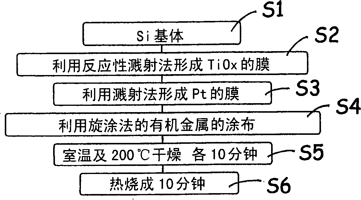
[0054] Below, refer to figure 2 The flow chart of the following describes the method of manufacturing the electrode 1 for electrolysis in Example 1 of the present invention. First, pretreatment of silicon constituting the base body 2 is performed as step S1. Here, silicon is preferably a material in which phosphorus (P), boron (B) and the like are introduced as impurities to increase electrical conductivity. As this silicon, a material with a very flat surface is used. Furthermore, in this embodiment, although silicon is used as the base body 2 , other conductive materials as described above may be used instead.

[0055] In this pretreatment, the silicon substrate 2 was treated with 5% hydrofluoric acid to remove the natural oxide film formed on the surface of the substrate 2 . In this way, the surface of the base body 2 becomes flatter. In addition, this preprocessing does not need to be performed. Thereafter, the surface of the substrate 2 is rinsed with pure water, an...

Embodiment 2

[0091] Below, refer to Figure 6 The flow chart of the following describes the method of manufacturing the electrode 21 for electrolysis according to the second embodiment of the present invention. and, Figure 7 A schematic configuration diagram of the electrolysis electrode 21 obtained in this example is shown. First, preprocessing of silicon constituting the base body 22 is performed in the same manner as in the above-described embodiment as step S11. Since the material of the base body 22 is the same as that of the above-mentioned embodiment, the description thereof is omitted. Thereafter, in step S12, it is introduced into a small chamber of an existing sputtering apparatus, and film formation is performed.

[0092] In step S12 , the adhesion layer 23 for improving the adhesion of the intermediate layer 24 as described above is formed on the surface of the base body 22 . The formation of the adhesion layer 23 on the base body 22 is performed by the reactive sputtering...

Embodiment 3

[0111] Next, the electrode for electrolysis of Example 3 of the present invention will be described. Because the manufacturing method of the electrode 31 for electrolysis obtained by utilizing this embodiment is the same as that of the above-mentioned embodiment 1 figure 2 The flow chart is the same as that of figure 1 Since they are substantially the same, description of the detailed manufacturing method is omitted.

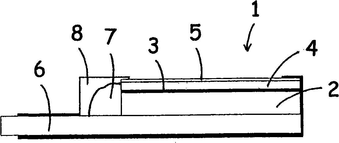
[0112] That is, the electrode for electrolysis in this embodiment is the same as in the above-mentioned embodiments. After forming the adhesion layer 3 with tantalum oxide by the sputtering method on the surface of the silicon constituting the substrate, it is formed on the surface of the adhesion layer 3 with platinum by the sputtering method. middle layer4.

[0113] Then, the surface layer 5 is formed on the surface of the substrate 2 on which the intermediate layer 4 is formed. In this embodiment, since the surface layer 5 is formed by the spin coating me...


PUM

PropertyMeasurementUnit
thicknessaaaaaaaaaa
thicknessaaaaaaaaaa
thicknessaaaaaaaaaa

Abstract

The present invention provides an electrode for electrolysis capable of efficiently forming ozone by electrolysis of an electrolytic solution (e.g., water) at ordinary temperature with a low current density, and an electrolysis unit using the electrode. The electrode for electrolysis includes a substrate and a surface layer formed on the surface of the substrate, and the surface layer is made of an amorphous insulator, for example, a thin film of amorphous tantalum oxide, amorphous tungsten oxide or amorphous aluminum oxide.

Description

technical field [0001] The invention relates to an electrolysis electrode used in industrial or civil electrolysis process. Background technique [0002] In general, ozone is a substance with very strong oxidizing power, and water in which ozone is dissolved, that is, so-called ozone water, is expected to be used in a wide range of cleaning and disinfection treatments such as cleaning of sewers, food, etc., and semiconductor device manufacturing processes. As a method of generating ozone water, a method of dissolving ozone generated by ultraviolet irradiation or electric discharge in water, a method of generating ozone in water by electrolysis of water, and the like are known. [0003] Patent Document 1 discloses an ozone water generating device that includes an ozone generating mechanism that generates ozone gas using an ultraviolet lamp and a tank that stores water, and generates ozone water by supplying the generated ozone gas to water in the tank. . In addition, Patent...

Claims


Application Information

Patent Timeline
Patent Type & Authority Applications(China)
IPC IPC(8): C25B11/04C25B1/13
CPCC25B1/13C25B9/19C25B11/075C25B11/053
Inventor 木塚健太金田和博池松峰男河田桂
Owner SANYO ELECTRIC CO LTD
Why Eureka
Try Eureka