
High efficiency energy-conserving barrier diaphragm capacitance deionization device

A capacitive deionization and energy-saving technology, applied in the direction of ion exchange water/sewage treatment, electrochemical water/sewage treatment, etc., can solve the problems affecting the electrode's electric adsorption capacity, achieve response speed, reusability, improve performance, reduce The effect of energy consumption

Active Publication Date: 2009-01-07
上海纳晶科技有限公司
View PDF0 Cites 34 Cited by
  • Summary
  • Abstract
  • Description
  • Claims
  • Application Information

AI Technical Summary

Problems solved by technology

However, during the regeneration process, the desorption of anions and the adsorption of cations on the surface of the anode and the desorption of cations and the adsorption of anions on the surface of the cathode exist simultaneously, which will seriously affect the electrosorption capacity of the regenerated electrode.

Method used


Image

  • High efficiency energy-conserving barrier diaphragm capacitance deionization device
  • High efficiency energy-conserving barrier diaphragm capacitance deionization device
  • High efficiency energy-conserving barrier diaphragm capacitance deionization device

Examples


Embodiment 1

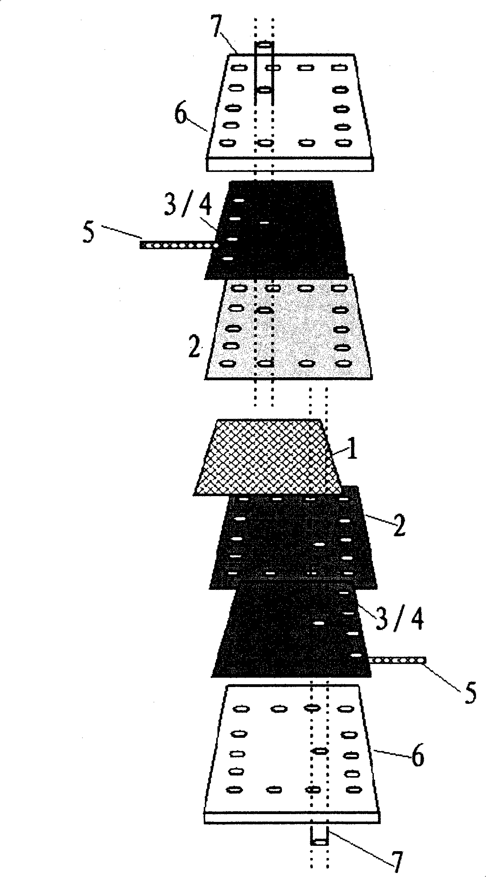
[0033] A diaphragm deionization capacitor unit, using a 100mm×100mm square graphite sheet as the conductive substrate 4, the thickness of the graphite sheet is 0.3mm, and a hole with a diameter of 6mm is drilled on the surface to allow water to pass through, and the surface of the graphite sheet is cleaned with acetone, Then prepare a layer of nickel metal catalyst layer on its surface by magnetron sputtering, and then use low-pressure chemical vapor deposition equipment to grow carbon nanotube-carbon fiber film on its surface as electrode 3, and the flow rates of acetylene and hydrogen are respectively 40sccm and 200sccm, The growth temperature is 550°C, and the growth time is 30 minutes;

[0034] The electrode lead wire 5 is made of carbon fiber wire; polypropylene cloth is used as the separator 1 with a thickness of 0.2mm; the supporting plate 6 is a plexiglass plate with a thickness of 5mm;

Embodiment 2

[0036] A diaphragm deionization capacitor unit, the electrode is 100mm × 200mm carbon airgel, the thickness is 0.5mm, and its surface is drilled with holes with a diameter of 8mm to allow water to pass through. The carbon airgel is prepared by the following method: Hydroquinone and formaldehyde are mixed at a molar ratio of 1:2, and secondary deionized water is added as a solvent and its mass percentage is adjusted, and Na 2 CO 3 As a catalyst, stir well to make the solution evenly mixed, move the mixed solution into a closed container, place it at room temperature for one day, then put it into a constant temperature box, and react at (85±3)°C for several days to generate red RF gas gel. Cut the airgel into a column, soak it in a suitable organic solvent for several hours, and change the organic solvent several times, so as to completely replace the water in the airgel. RF aerogels with continuous network structure were obtained by drying the soaked aerogels in the air for s...


PUM


Abstract

The invention relates to the technical field of capacitance deionization devices, in particular to a high-efficient and energy-saving capacitance deionization device, which is characterized in that an ion exchange membrane (2) is added between a partition board (1) and an electrode (3); water ports (7) are arranged on both an upper support plate and a lower support plate (6); and the upper water port and the lower water port are arranged in a staggered manner. Compared with the prior art, the device adopts compact and multiporous carbon-based material as capacitance deionization electrodes, and adds the ion exchange membrane, so that the device is thin and light, the structure is optimized, the absorption performance is improved, and the voltage imposed on the electrode in operation is reduced; therefore, the energy consumption, the manufacture cost and the use cost of the device are greatly reduced, the ion absorption efficiency is high, the stability is good, the service life is long, the power consumption is low, the response speed is high, the device can be used repeatedly, etc.

Description

[technical field] [0001] The invention relates to the technical field of capacitive deionization devices, in particular to a high-efficiency and energy-saving diaphragm capacitive deionization device. [technical background] [0002] Global scarcity of freshwater resources and growing populations are driving an ever-increasing demand for water, especially in cities located in arid regions. However, how to use four-fifths of the ocean and lake water on the earth has not been completely resolved so far. Mainly the natural water in oceans, lakes and rivers contains various pathogenic microorganisms and toxic organic substances, suspended solids, heavy metals and many inorganic salts. Even the tap water that leaves the factory from the waterworks is polluted to varying degrees when it arrives at the user due to pipeline pollution. In order to purify these water bodies, sterilization, filtration of suspended solids and desalination must be carried out. At the same time, people m...

Claims


Application Information

Patent Timeline
IPC IPC(8): C02F1/46C02F1/42
Inventor 孙卓潘丽坤高阳李海波
Owner 上海纳晶科技有限公司
Learn More