
Method and ion source for direct ionization of sample of low-temperature plasma

A plasma and plasma torch technology, applied in the field of direct ionization of samples by ions, can solve the problems of reducing the service life of electrodes, increasing operating costs, inability to use metals, etc., and achieving the effects of avoiding pollution, convenient operation and small size

Inactive Publication Date: 2009-08-19
TSINGHUA UNIV +1
View PDF0 Cites 37 Cited by
  • Summary
  • Abstract
  • Description
  • Claims
  • Application Information

AI Technical Summary

Problems solved by technology

The glow discharge ion source device is simple and the operating cost is low, but it requires a certain degree of vacuum, so vacuum equipment is necessary, which leads to the complexity of the instrument design and increases the operating cost; and the electrodes of the glow discharge Direct contact with the sample will pollute the electrode and reduce the service life of the electrode
The previously developed dielectric barrier discharge ion source device consisting of rod-shaped electrodes and flat-plate electrodes has simple structure, low gas flow rate, less pollution and low cost. It can complete the direct desorption and ionization of solid samples under atmospheric pressure, but the two electrodes On both sides of the medium, the shape, size, and thickness of the sample are limited by the space between the electrodes and the medium; in addition, the medium between the two electrodes is not only an insulating barrier medium, but also a stage, so metal cannot be used as a sample carrier

Method used


Image

  • Method and ion source for direct ionization of sample of low-temperature plasma
  • Method and ion source for direct ionization of sample of low-temperature plasma
  • Method and ion source for direct ionization of sample of low-temperature plasma

Examples


Embodiment 1

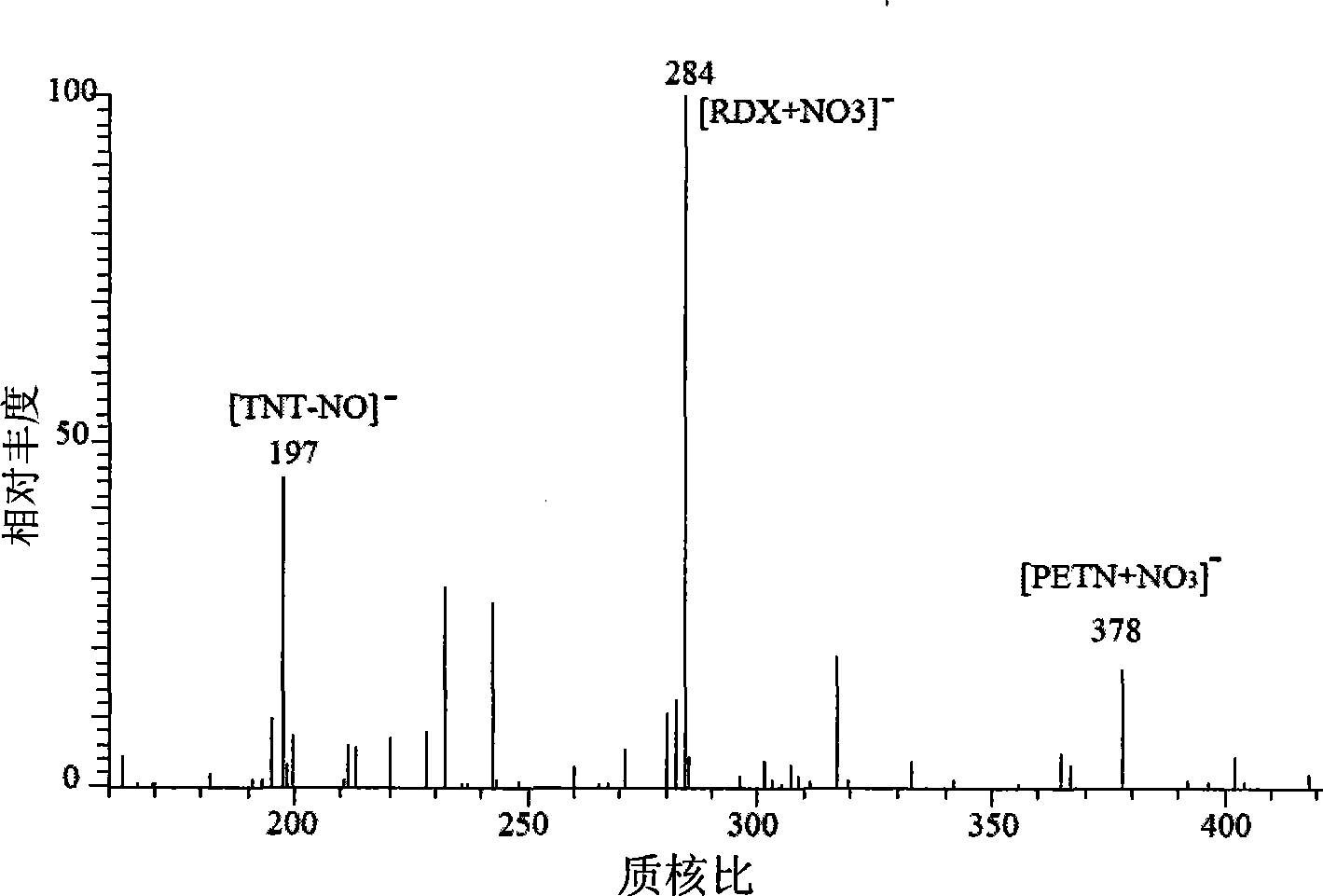
[0038] Embodiment 1, carry out mass spectrometry analysis to three kinds of explosive mixture samples

[0039] The mixed samples of three explosives were selected for mass spectrometry analysis, the three explosives were: 2,4,6-trinitrotoluene (TNT), RDX (RDX), and passivated Taian (PETN).

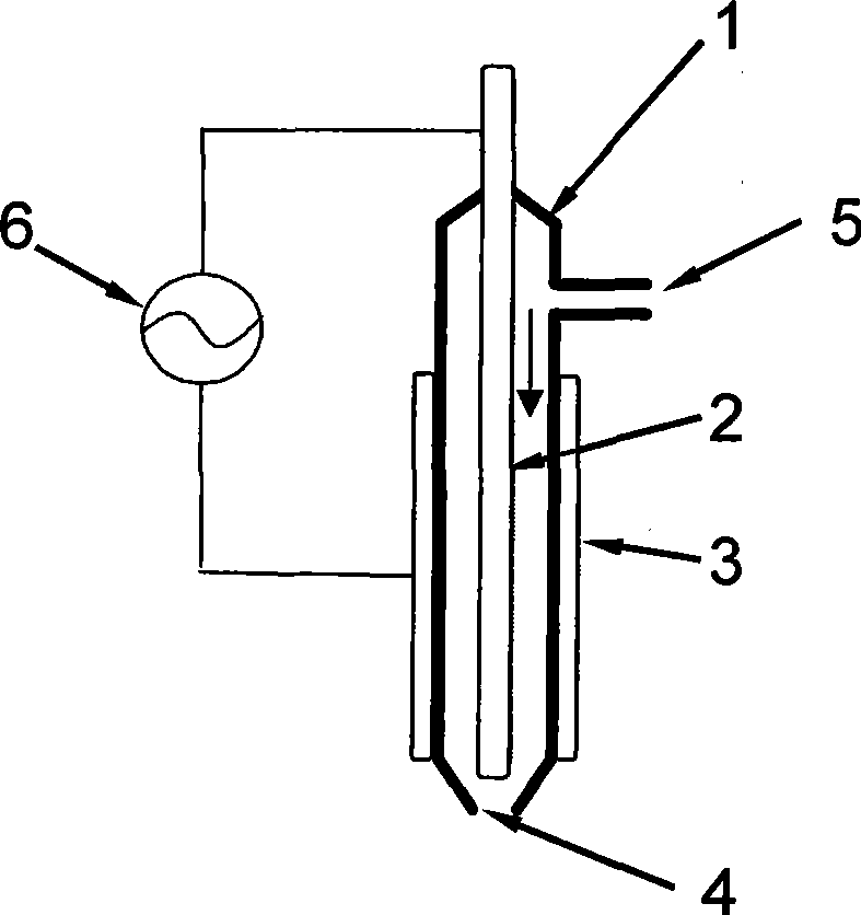
[0040] The structure of the ion source used is as follows figure 1 As shown, the details are as follows: It has an insulating dielectric tube, an inner electrode, an outer electrode, a power supply device, and a working gas inlet and a plasma torch flame outlet, wherein the insulating dielectric tube is a straight hollow tube with inward shrinkage openings at both ends, The power supply device is a high-voltage AC power supply, the inner electrode is a rod-shaped electrode, and the outer electrode is a tubular electrode; one end opening of the insulating medium tube is the plasma torch flame outlet; the inner electrode is sleeved on the other end opening of the insulating medium tube In t...

Embodiment 2

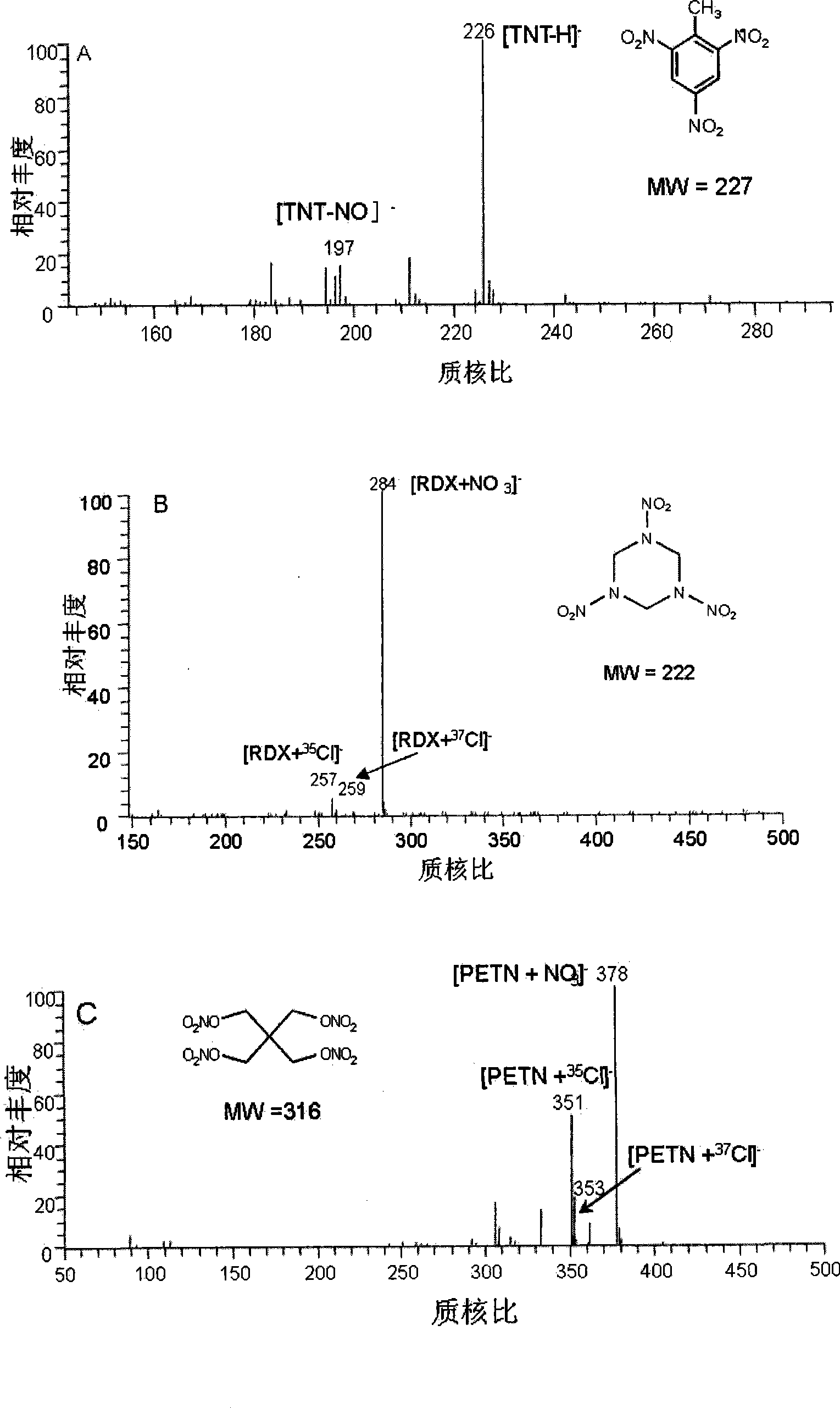
[0043] Embodiment 2, mass spectrometry is carried out to explosive sample

[0044] Three kinds of explosive samples were selected for mass spectrometry analysis, respectively: 2,4,6-trinitrotoluene (TNT), RDX, and passivated Taian (PETN).

[0045] The ion source used is the same as in Example 1. Select three kinds of explosives (TNT, RDX and PETN) respectively with solvent (CH 3 OH / H 2 O=1:1 (volume ratio)) and solvent (CH 3 OH / H 2 O=1:1 (volume ratio), add HCl concentration 0.05%) to dissolve and dilute, and make a single-component solution containing 50ng PETN or 50ng RDX or 50ngTNT in 1 μ L solution for future use. Spot 1uL each of solvent and explosive sample solution on a glass slide, and dry at room temperature 25°C. In the negative ion mode, feed the ion source with carrier gas argon, adjust the gas flow rate to 250mL / min, the voltage is 3.5-4.5kV, the frequency is 18-30kHz, the power supply is 2.5W, and the sample is moved to a distance from the ion source after t...

Embodiment 3

[0047] Embodiment 3, carry out mass spectrometry analysis to four kinds of amino acid mixture samples

[0048] Select four amino acid mixture samples for mass spectrometry analysis, these four amino acids are: L-alanine (MW=89), L-valine (MW=117), L-phenylalanine (MW=165) , L-Tryptophan (MW=205).

[0049] The ion source used is the same as in Example 1. Dissolve the above four amino acids with secondary water to form a mixed solution. The analysis method is the same as in Example 1. The gas flow rate is 200mL / min, the voltage is 3.5-4.5kV, the frequency is 18-30kHz, the power supply is 5W, and the mass spectrogram is recorded as Figure 4 As shown, the characteristic signals of four amino acids are L-alanine (m / z90, m / z72), L-valine (m / z118, m / z72), L-phenylalanine (m / z166, m / z120), L-tryptophan (m / z205, m / z188). In the figure, the protonated molecular ion peaks and fragment peaks of each amino acid can be clearly distinguished, indicating that the ionization method and ion...


PUM

PropertyMeasurementUnit
Lengthaaaaaaaaaa
Lengthaaaaaaaaaa
The inside diameter ofaaaaaaaaaa

Abstract

The invention discloses a method for directly ionizing samples by low-temperature plasma, and an ion source thereof. The ion source comprises an insulated dielectric tube (1), an inner electrode (2), an outer electrode (3), a working gas inlet (5) and a plasma torch outlet (4). The insulated dielectric tube is a hollow tube with both ends provided with openings contracting inward, and the inner electrode is a bar-shaped electrode or an electrode taking the shape of an hollow tube, and the outer electrode is a bar-shaped electrode; one of the openings contracting inward at both ends of the insulated dielectric tube is a plasma torch outlet; the inner electrode is sheathed on the insulated dielectric tube through the other opening of the insulated dielectric tube, and one end of the inner electrode runs out of the insulated dielectric tube while the other end is positioned in the insulated dielectric tube; the outer electrode covers the insulated dielectric tube. The ion source can determine various organic substances under the atmospheric pressure, with high ionization efficiency and no limitation to the size, the shape and the thickness of samples to be tested. Furthermore, the iron source is applicable to carriers of various materials.

Description

technical field [0001] The invention relates to a method for directly ionizing a sample with low-temperature plasma and an ion source thereof. Background technique [0002] Mass spectrometry is one of the most sensitive and widely used analytical methods known at present. The mass spectrometer used in this method includes two basic structural units, an ion source and a mass analyzer. Among them, the ion source is the advancement of sample ionization technology. key issues. At present, there are many kinds of ion sources, such as electron bombardment ion source (EI), chemical ionization source (CI), field ionization / field desorption ionization source (FI / FD), fast atom bombardment source (FAB), electrospray ionization Source (ESI), Laser Desorption Source (LD), Atmospheric Pressure Chemical Ionization Source (APCI), etc. Before the determination of these ion sources, the sample needs to go through a tedious pretreatment process, and the sample cannot be desorbed and ionized ...

Claims


Application Information

Patent Timeline
IPC IPC(8): H01J49/12G01N21/73G01N27/64
Inventor 张新荣张焱杨成对张四纯马潇潇文芳
Owner TSINGHUA UNIV
Learn More