
Jacking flue gas processing device and method

A flue gas treatment, top entry technology, applied in separation methods, chemical instruments and methods, dispersed particle separation, etc., to achieve superior ammonia escape control effect, control of ammonia escape loss, and compact equipment.

Inactive Publication Date: 2009-10-07
娄爱娟
View PDF5 Cites 6 Cited by
  • Summary
  • Abstract
  • Description
  • Claims
  • Application Information

AI Technical Summary

Problems solved by technology

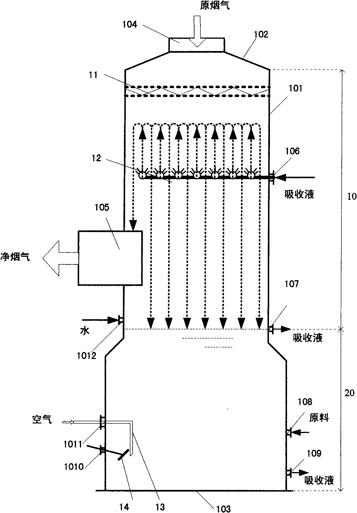
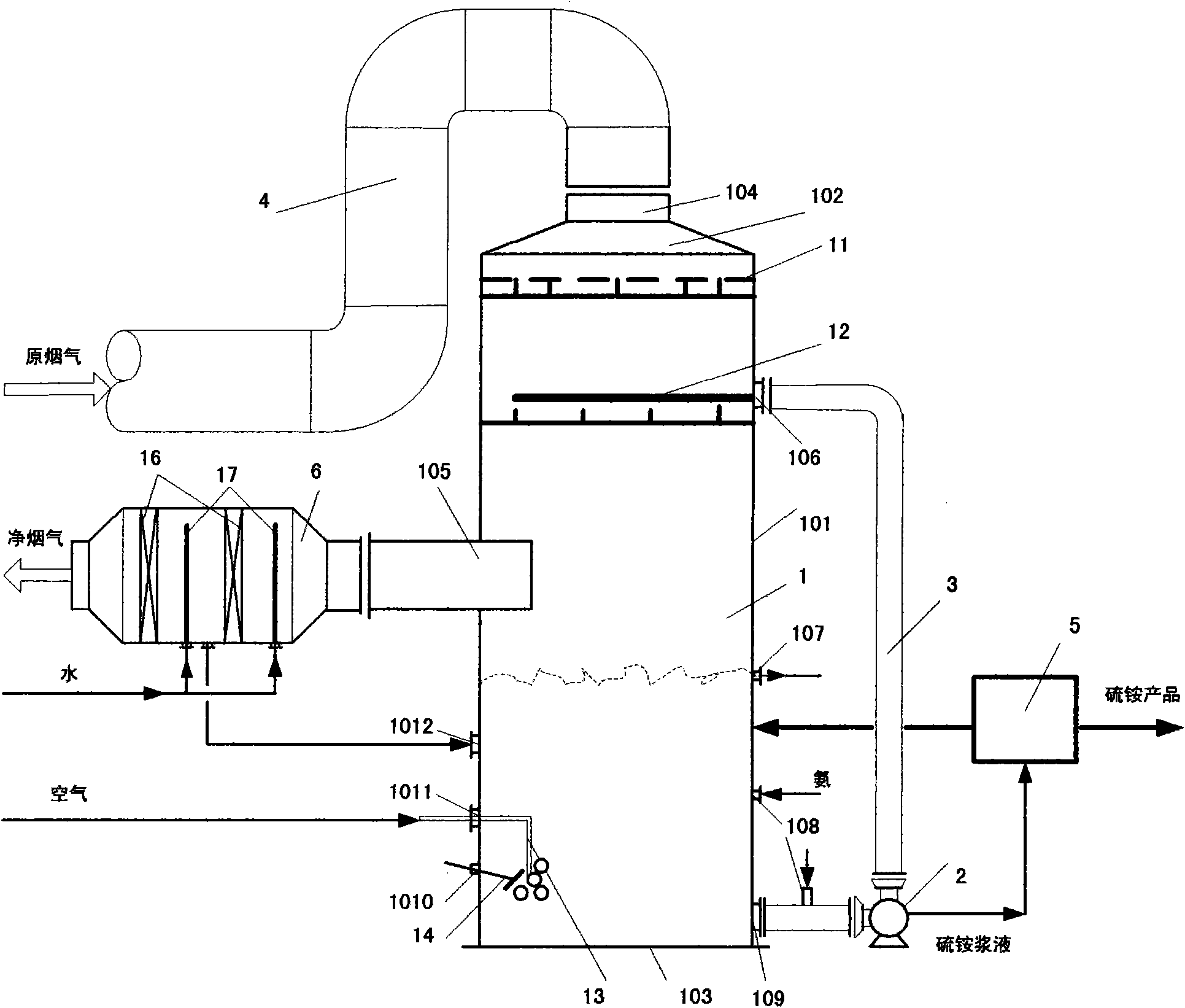
[0013] The technical problem to be solved in the present invention is to disclose a new type of flue gas treatment, i.e. a flue gas desulfurization device, specifically a flue gas desulfurization tower, and a flue gas treatment or desulfurization method using the flue gas device, which has higher Excellent mass transfer efficiency and the performance of controlling ammonia escape and waste, and can optimize water utilization and simplify equipment structure

Method used


Image

  • Jacking flue gas processing device and method
  • Jacking flue gas processing device and method

Examples


Embodiment 1

[0046] A 260T / h coal-fired power boiler uses high-sulfur coal with a sulfur content of 3.0%, and its flue gas flow rate is 320,000m 3 / h, flue gas containing sulfur dioxide 8,500mg / Nm 3 , containing smoke dust 80mg / Nm 3 , the content of other components, such as sulfur trioxide, nitrogen oxide and hydrogen chloride or hydrogen fluoride, could not be determined, and the flue gas temperature was 135°C.

[0047] With the desulfurization method of the present invention, flue gas containing pollutants such as sulfur dioxide and soot and having a temperature greater than 100°C, or called raw flue gas, enters the absorber 10 from the flue gas inlet 104 at the top of the desulfurization tower 1, and is absorbed After the flue gas distributor 11 installed in the device 10 is evenly distributed, it contacts with the absorption liquid mist droplets containing ammonia sprayed upward from the absorption liquid sprayer 12 at the same time in countercurrent and downstream contact, mixing, h...

Embodiment 2

[0054] A 260T / h coal-fired power boiler uses high-sulfur coal with a sulfur content of 0.6%, and its flue gas flow rate is 320,000m 3 / h, flue gas containing sulfur dioxide 1400mg / Nm 3 , containing smoke dust 40mg / Nm 3 , the content of other components, such as sulfur trioxide, nitrogen oxide and hydrogen chloride or hydrogen fluoride, could not be determined, and the flue gas temperature was 125°C.

[0055] Adopt the method of the present invention, be identical with embodiment 1.

[0056] The raw material ammonia is ammonia water with an ammonia content of 18.0%, and the addition amount is 1260kg / h, and the pH value of the absorption liquid is maintained at 5.3. The ammonia water is continuously added to the absorption liquid, and the addition position is on the absorption liquid circulation line 3, specifically The ammonia arranged on the circulation pipe 3 between the absorption liquid circulation outlet 109 of the oxidation crystallizer 20 and the inlet of the circulati...


PUM


Abstract

The invention discloses a new jacking flue gas processing device and a method thereof. Flue gas enters from the top of the device, and ammoniated alkali absorption liquid absorbs acid gas of the flue gas, thereby realizing multifunctional integration process of oxidation and crystallization. The invention is characterized in that a provided flue gas uniform distribution machine and an upwardly mounted atomizing nozzle enable gas-liquid two-phase to have impact jet contact, in particular simultaneous contact of back flow and parallel flow of the flue gas with the absorption liquid is formed above an absorption liquid spray thrower, thereby finishing main processing task and canceling a cold shocking water spray member installed in other technologies; the flue gas is contacted with the absorption liquid in parallel flow, thereby further improving the processing efficiency, and simultaneously efficiently controlling the escape loss of ammonia; a parallel flow demister with high efficiency and compact device is used, so wide application is expected in the filed of flue gas purification.

Description

technical field [0001] The invention relates to a flue gas treatment device and method, in particular to a desulfurization device and method for recovering sulfur oxides in flue gas with ammonia as a raw material to produce useful products with high added value, belonging to the technical fields of electric power, metallurgy, environmental protection and chemical industry. Background technique [0002] The continuous development of the economy has made the environmental protection requirements of industrial production equipment higher and higher. Flue gas, or flue gas and flue gas desulfurization (FGD, Flue Gas Desulfurization), or flue gas scrubbing (Scrubbing) is an exhaust gas treatment and environmental protection facility that must be equipped in today's combustion or oil-fired power plants, and steel plants. In China, environmental protection laws and regulations on flue gas desulfurization have been enacted for many years and have been strictly implemented. Penalties ...

Claims


Application Information

Patent Timeline
Patent Type & Authority Applications(China)
IPC IPC(8): B01D53/78B01D53/50
Inventor 娄爱娟
Owner 娄爱娟
Learn More