Air separation method utilizing liquefied natural gas cold energy

A technology for the separation of liquefied natural gas and air, applied in the direction of cold treatment separation, liquefaction, refrigeration and liquefaction, etc., can solve the problems of high unit energy consumption, underutilization of high-temperature cold energy, high shaft power of raw material air compressors, etc., and achieve unit power consumption Reduced, obvious social and economic benefits, the effect of saving cooling water

Active Publication Date: 2009-11-04
CHINA NAT OFFSHORE OIL CORP +3
View PDF4 Cites 25 Cited by
  • Summary
  • Abstract
  • Description
  • Claims
  • Application Information

AI Technical Summary

Problems solved by technology

[0004] Chinese patent application specification CN 1873357A discloses an air separation method for recovering the cold energy of liquefied natural gas. The low-temperature nitrogen compressor of the patent application only has one stage of compression, the inlet temperature is -110°C to -120°C, and the outlet pressure is 3.0 to 3.5MPa; There is a booster turbo expander in the cycle; the intake air is cooled by cold nitrogen; because the cold energy of LNG is not fully utilized, and the product extraction rate of the patented rectification system is low, the unit energy consumption of the product is relatively high
[0006] Chinese patent application specification CN 101050913A discloses an air separation method for producing liquid oxygen and liquid nitrogen by using the cold extracted from liquefied natural gas. Temperature and exhaust pressure; the extraction rate of oxygen and argon in the rectification tissue of the patent application is low; the patent application does not have an ethylene glycol aqueous solution cooling system, not only the shaft power of the raw material air compressor is high, but the high-temperature cooling energy of NG is not sufficient Utilization, resulting in high unit energy consumption of the product, and the NG exiting the air separation system is still at low temperature, which cannot meet the pipeline transportation requirements
[0007] Chinese patent application specification CN 1407303A discloses an air separation device using the cooling capacity of liquefied natural gas. The patent application does not specify what kind of nitrogen compressor is used, and there is no ethylene glycol aqueous solution cooling system, which is only suitable for small air separation equipment
[0008] None of the above-mentioned patent application descriptions involves measures to detect possible LNG leakage in time, which is more likely to cause some problems and accidents

Method used


Image

  • Air separation method utilizing liquefied natural gas cold energy
  • Air separation method utilizing liquefied natural gas cold energy
  • Air separation method utilizing liquefied natural gas cold energy

Examples


Embodiment 1

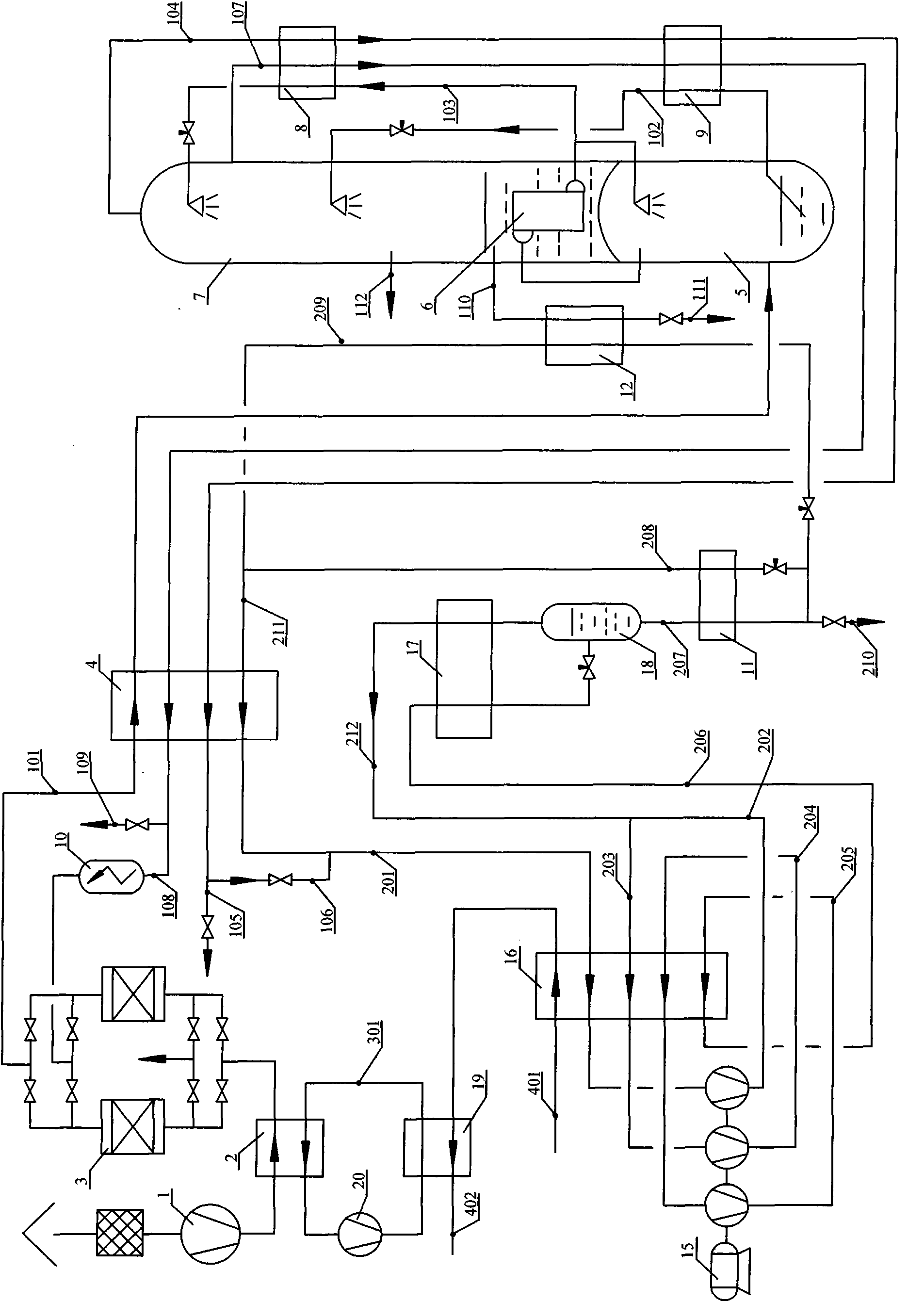
[0034] Such as figure 1 As shown, the air 101 sucked from the atmospheric air through the filter reaches the required pressure of about 0.5Mpa through multi-stage compression (intercooler is cooled with ethylene glycol aqueous solution), and then cools down with ethylene glycol aqueous solution in the final cooler 2, and then Into the air purification system 3 to remove carbon dioxide, water, acetylene and other harmful impurities and then sent to the main cold box of the air separation unit. The purified air is sent to the lower tower 5 after the main heat exchanger 4 exchanges heat with the reflux gas and cools down to the required temperature. The air is preliminarily separated in the lower tower 5 to obtain oxygen-enriched liquid air 102 at the bottom and pure nitrogen at the top. The pure nitrogen enters the main condensing evaporator 6, where it is condensed into liquid nitrogen by liquid oxygen. A part of the liquid nitrogen is sent back to the lower tower to maintain...

Embodiment 2

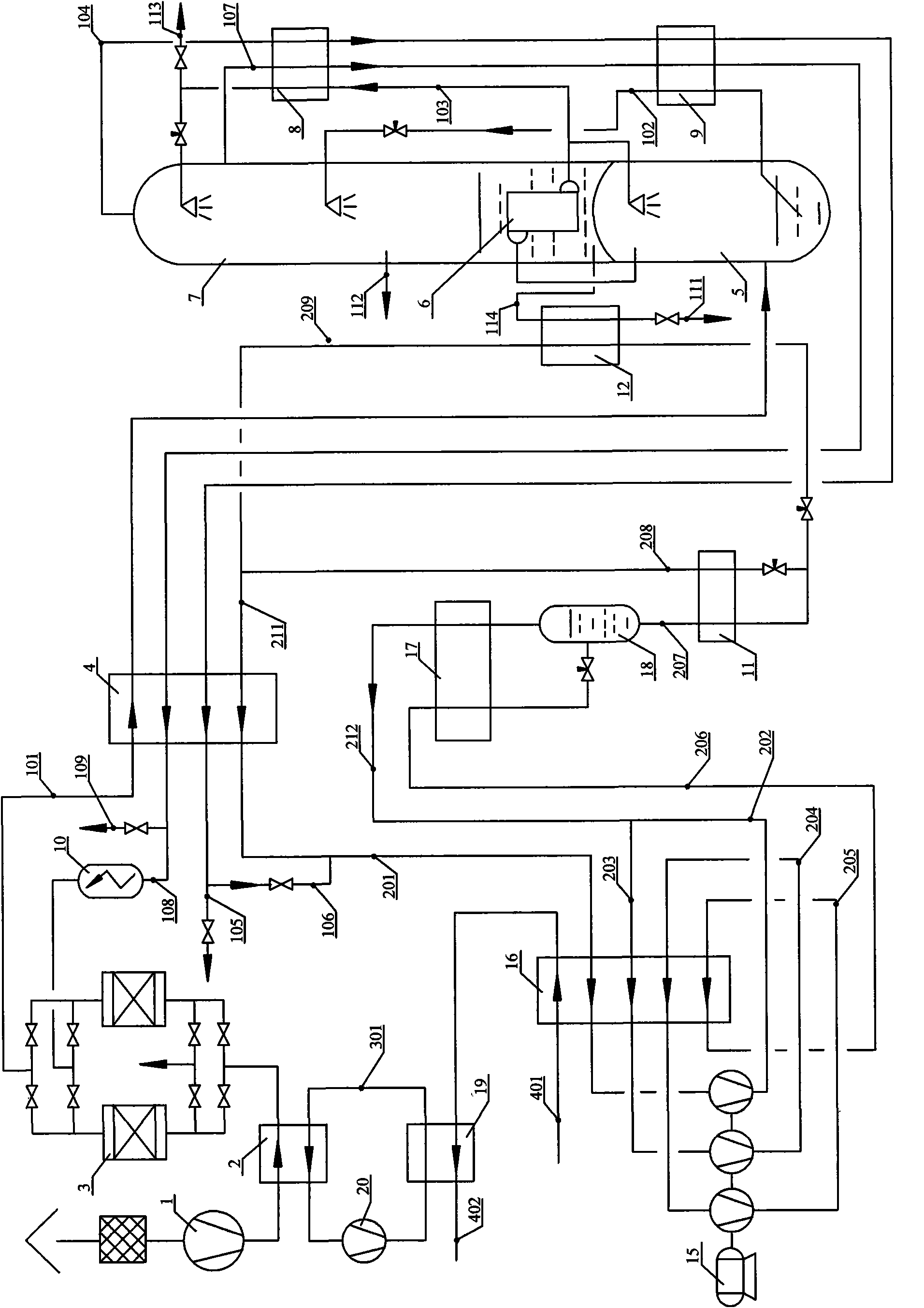
[0039] Such as figure 2 As shown, the difference from Example 1 is mainly that liquid oxygen and liquid nitrogen products are produced by rectification. The refrigerant liquid nitrogen 207 used to transfer the cold energy of LNG is further subcooled and divided into two paths: one path is throttled to a low pressure to supercool itself, and the other path is throttled to supercool the liquid oxygen 114 extracted from the bottom of the upper tower 7 . The low-pressure nitrogen-gas-liquid mixture 208 and 209 are combined to form a low-pressure gas 211 , and the feed air 101 is partially condensed in the main heat exchanger 4 . The raw material air 101 enters the lower tower 5 after being partially condensed, and the liquid nitrogen 103 extracted from the main condensing evaporator after being rectified by the lower tower 5 and the upper tower 7 is sent to the upper tower through throttling after being supercooled by the liquid nitrogen subcooler 8 7. The top part participates ...

Embodiment 3

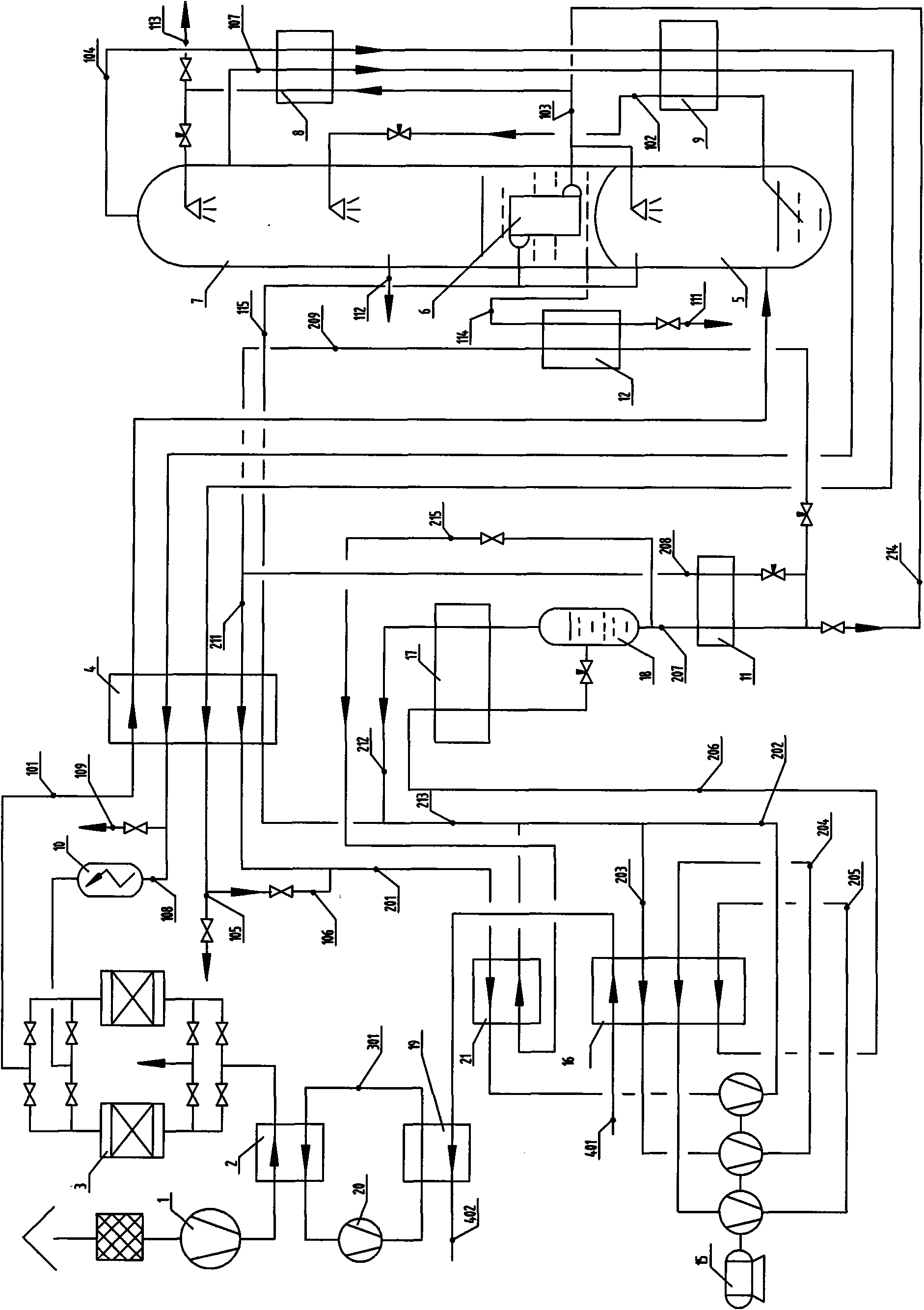
[0044] Such as image 3 As shown, the difference between this embodiment and Embodiment 1 is: after ensuring that LNG will not leak into the refrigerant liquid nitrogen 207 that exchanges heat with it, one path of liquid nitrogen 214 can be separated from the refrigerant liquid nitrogen 207 and the main condensation and evaporation The liquid nitrogen 103 in the container 6 is combined, and after cooling, a small part becomes the liquid nitrogen product 113, most of which enter the top of the upper tower 7 to participate in rectification, and provide the required cooling capacity for the separation process. At this time, what is extracted from the bottom of the upper tower 7 is liquid oxygen 114 . In addition, a stream of nitrogen gas 115 is drawn from the top of the lower tower 5 to the main heat exchanger 4 . The medium-pressure nitrogen 115 merges with the medium-pressure nitrogen 212 to form the medium-pressure nitrogen 213 after reheating in the main heat exchanger 4 and...


PUM


Abstract

The invention discloses an air separation method utilizing liquefied natural gas cold energy, comprising an air separation unit, an LNG cold energy utilization unit providing refrigeration energy for the LNG cold energy utilization unit and a glycol water solution circulation unit utilizing NG high temperature cold energy. In the invention, low temperature cold energy of the LNG is applied to the air separation system, thus unit power consumption of a liquid air separation product can be reduced to about 0.30kwh/m, which is one third of the unit power consumption of a liquid air separation product in conventional process production; and unit power consumption of the internal compressed gas product also can be greatly reduced, and meanwhile a large number of cooling water can be saved, thus being in accordance with the trend of energy saving, consumption reduction and circular economy developing and having obvious social benefit and economic benefit.

Description

technical field [0001] The invention relates to an air separation method, in particular to an air separation method utilizing the cold energy of liquefied natural gas. Background technique [0002] LNG (liquefied natural gas) is a high-quality clean energy. In order to meet the requirements of pipeline transportation, LNG needs to be pressurized to a specified pressure. During pressurization, part of the cold energy of LNG is converted into pressure energy. The pressurized LNG still has high-grade low-temperature cold energy. The usual way is to use seawater heating to gasify and heat up and send it to the gas pipeline. This wastes precious low-temperature cold energy. [0003] Air separation method, especially the air separation method for producing liquid air separation products such as liquid oxygen, liquid nitrogen and liquid argon, and the air separation method for producing part of pressurized gas oxygen, gas nitrogen (internal compressed gas product) and part of l...

Claims


Application Information

Patent Timeline
Patent Type & Authority Applications(China)
IPC IPC(8): F25J3/04
CPCF25J3/04157F25J3/0406F25J3/04224F25J3/04272F25J3/04351F25J3/04412F25J2210/62F25J2270/02F25J2270/12F25J2270/42F25J2270/904
Inventor 张磊江楚标单金铭薛鲁
Owner CHINA NAT OFFSHORE OIL CORP
Why Eureka
Try Eureka