
Device and method for chemical hydride catalytic-hydrolysis hydrogen production suitable for onboard hydrogen source

A hydrogen production device and a technology for catalytic hydrolysis, applied in the field of hydrogen storage and hydrogen production, can solve the problems of rapid response, reduced hydrogen storage density, and large fluctuation of hydrogen pressure, so as to improve the hydrogen production rate, reduce the volume, and increase the fuel. The effect of fluid velocity

Inactive Publication Date: 2009-12-09
INST OF METAL RESEARCH - CHINESE ACAD OF SCI
View PDF0 Cites 24 Cited by
  • Summary
  • Abstract
  • Description
  • Claims
  • Application Information

AI Technical Summary

Problems solved by technology

In terms of hydrogen production process control, the pressure control fuel pump opening and closing design is mostly used at present. Because the fuel pump has only two working states, this control / operation mode is difficult to respond quickly to the hydrogen supply demand of the hydrogen terminal; at the same time , due to the large fluctuations in the hydrogen pressure of the system, it is necessary to increase the hydrogen supply capacity of the system by increasing the volume of the hydrogen buffer tank, resulting in a decrease in the weight / volume hydrogen storage density of the system

Method used


Image

  • Device and method for chemical hydride catalytic-hydrolysis hydrogen production suitable for onboard hydrogen source
  • Device and method for chemical hydride catalytic-hydrolysis hydrogen production suitable for onboard hydrogen source
  • Device and method for chemical hydride catalytic-hydrolysis hydrogen production suitable for onboard hydrogen source

Examples


Embodiment 1

[0049] Comparison of hydrogen production performance of devices using different types of catalytic reaction chambers.

[0050] Device and operating conditions:

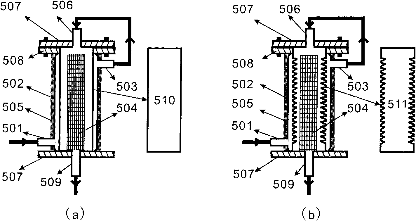
[0051] Three kinds of catalytic reaction chambers were compared and studied: the traditional straight-tube catalytic reaction chamber, and the straight-tube catalytic reaction chamber with a jacketed heat exchanger (such as figure 2 (a)) and a bellows-type catalytic reaction chamber with a jacketed heat exchanger (such as figure 2As shown in (b), the dimensions of the three catalytic reaction chambers are Φ20mm (inner diameter) × 1.5mm (wall thickness) × 300mm (length), and the material of the catalytic reaction chamber is stainless steel. Using Co-W-B / foam nickel catalyst (Co-W-B alloy loading capacity is 43wt.%), foam nickel carrier purity is 99.99wt.%, thickness is 1.88mm, surface density is 575g / m 2 , the average pore size is 0.2-0.5mm, and the catalyst mass is 33g. The composition of the fuel liquid used is:...

Embodiment 2

[0056] The hydrogen production performance of the traditional straight-tube catalytic reaction chamber, the bellows catalytic reaction chamber with external spiral heat exchanger and the straight-tube catalytic reaction chamber with built-in spiral heat exchanger were compared and studied.

[0057] Device and operating conditions:

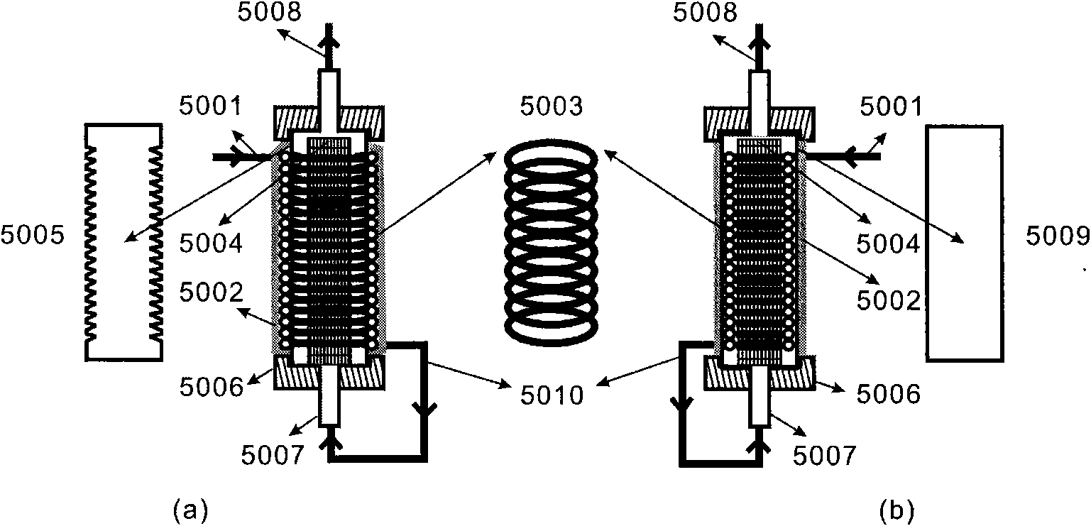
[0058] Bellows catalytic reaction chamber with external spiral heat exchanger (such as image 3 (a) shown) and the device structure of the straight tube catalytic reaction chamber with built-in spiral heat exchanger (such as image 3 As shown in (b), the dimensions of the three catalytic reaction chambers are Φ20mm (inner diameter)×1.5mm (wall thickness)×300mm (length), and the material of the catalytic reaction chambers is titanium. Using Co-Ru / TiO 2 Catalyst (Co-Ru alloy loading is 14wt.%), TiO 2 The purity is 99.9wt.%, the average particle size is about 100 mesh, and the specific surface area is about 80m 2 / g, the catalyst mass is 55g, and ...

Embodiment 3

[0061] The effect of adding an automatic control unit on the response time of the hydrolysis hydrogen production unit was studied.

[0062] Device and operating conditions:

[0063] A bellows type catalytic reaction chamber with an external jacketed heat exchanger is constructed as follows: figure 2 As shown in (b), the reaction chamber size, material and device hydrogen production rate measurement method are the same as in Example 1. Using Ni-Pt / graphite catalyst (Ni-Pt load is 10wt.%), the purity of graphite support is 99.9wt.%, the average particle size is 50 mesh, and the specific surface area is 30m 2 / g, the catalyst quality is 65g, and the catalyst is coated with 100 mesh stainless steel mesh. The fuel used is 20wt.% NaBH 4 +3wt.% NaOH+77wt.%H 2 O, the operating conditions are 24°C and the pressure is 0.45MPa. After the hydrogen produced was dehydrated by a silica gel drier, the hydrogen production rate was measured by a gas mass flow meter.

[0064] Figure 7 T...


PUM

PropertyMeasurementUnit
The average particle sizeaaaaaaaaaa
Areal densityaaaaaaaaaa
Average pore sizeaaaaaaaaaa

Abstract

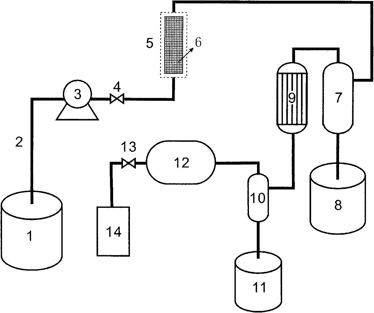
The invention relates to a hydrogen storage and production technology, in particular to a device and a method for chemical hydride catalytic-hydrolysis hydrogen production suitable for an onboard hydrogen source. The hydrogen production device mainly comprises a catalytic reaction chamber provided with a heat exchanger, a gas-liquid separator, a fuel pump and a controlling unit, and the hydrogen production method is used for controlling the contact and the separation between liquid fuel and catalyst to achieve the purpose of prompt hydrogen production as required. Since the heat exchanger is additionally arranged at the periphery or inside the catalytic reaction chamber, the heat from hydrolysis reaction is effectively utilized, the initial temperature of the liquid fuel is remarkably improved, the hydrogen-production rate of the device, the fuel conversion ratio and the system energy efficiency are greatly improved; and in addition, due to the design of the controlling unit, the continuous automatic adjustment of the delivery rate of the liquid fuel is realized, the stable hydrogen pressure of the system is ensured, and the hydrogen-storage density of the device is improved when the hydrogen supply demand at the hydrogen use terminal is responded in real time. The provided device for prompting hydrogen production can provide the onboard hydrogen source for hydrogen fuel-cell vehicles and various military and civil portable power supplies.

Description

technical field [0001] The invention relates to hydrogen storage and hydrogen production technology, in particular to a chemical hydride catalytic hydrolysis hydrogen production device and method suitable for mobile hydrogen sources. Background technique [0002] Developing high-performance hydrogen storage systems to provide mobile hydrogen sources for hydrogen fuel cell vehicles and various military and civilian portable power sources is a key link in the application of hydrogen energy. Compared with high-pressure hydrogen containers and low-temperature liquid hydrogen, material-based solid-state hydrogen storage has significant advantages in terms of operational safety, energy efficiency, and volumetric hydrogen storage density, and is recognized as the most promising hydrogen storage method. However, many years of research have shown that none of the known reversible hydrogen storage materials can meet the comprehensive performance requirements of the vehicle-mounted hyd...

Claims


Application Information

Patent Timeline
IPC IPC(8): C01B3/02C01B3/06C01B3/08
CPCY02E60/362Y02E60/36Y02P20/10
Inventor 王平戴洪斌梁艳马来鹏
Owner INST OF METAL RESEARCH - CHINESE ACAD OF SCI
Learn More