
Preparation method of lithium silicon alloy membrane electrode used for lithium ion battery

A technology of lithium-ion batteries and lithium-silicon alloys, applied in battery electrodes, electrode manufacturing, circuits, etc., can solve problems such as difficult process control, difficult large-scale production, and complex processes, achieving good adhesion, reducing impact, and effective The effect of regulating the circulation capacity

Inactive Publication Date: 2010-03-10
SHANGHAI JIAO TONG UNIV
View PDF1 Cites 18 Cited by
  • Summary
  • Abstract
  • Description
  • Claims
  • Application Information

AI Technical Summary

Problems solved by technology

[0006] Electrochimica Acta magazine, Volume 53, 2008, page 8149, reported the preparation of a 300nm thick amorphous Si-Al film by magnetron sputtering, with a mass percentage of Al of 18.08%, and a specific capacity of 2100mAh g in the first 10 cycles at a rate of 0.5C. -1 , excellent cycle performance, the capacity retention rate after 350 cycles is 80.2%; the reversible capacity of several micron thick amorphous silicon film electrodes prepared by Sanyo Corporation of Japan using RF magnetron sputtering technology reaches 3000mAh g -1 Above, the efficiency is close to 100%, and the electrode can be cycled stably for dozens of times. However, the morphology and performance of the thin film electrode are affected by many factors such as the roughness of the copper substrate, the properties of the Si / Cu interface, and the thickness of the silicon film. The result is a reproducible process. It is difficult to control (M.Shima, H.Yagi, et.al., US patent 6887511B1(2005))
[0007] Although the silicon-based thin film material prepared by the above method has high capacity and excellent cycle performance, special equipment is required for material preparation, and the process is complicated and the cost is high, making it difficult to mass-produce rapidly.

Method used


Image

  • Preparation method of lithium silicon alloy membrane electrode used for lithium ion battery
  • Preparation method of lithium silicon alloy membrane electrode used for lithium ion battery
  • Preparation method of lithium silicon alloy membrane electrode used for lithium ion battery

Examples


Embodiment 1

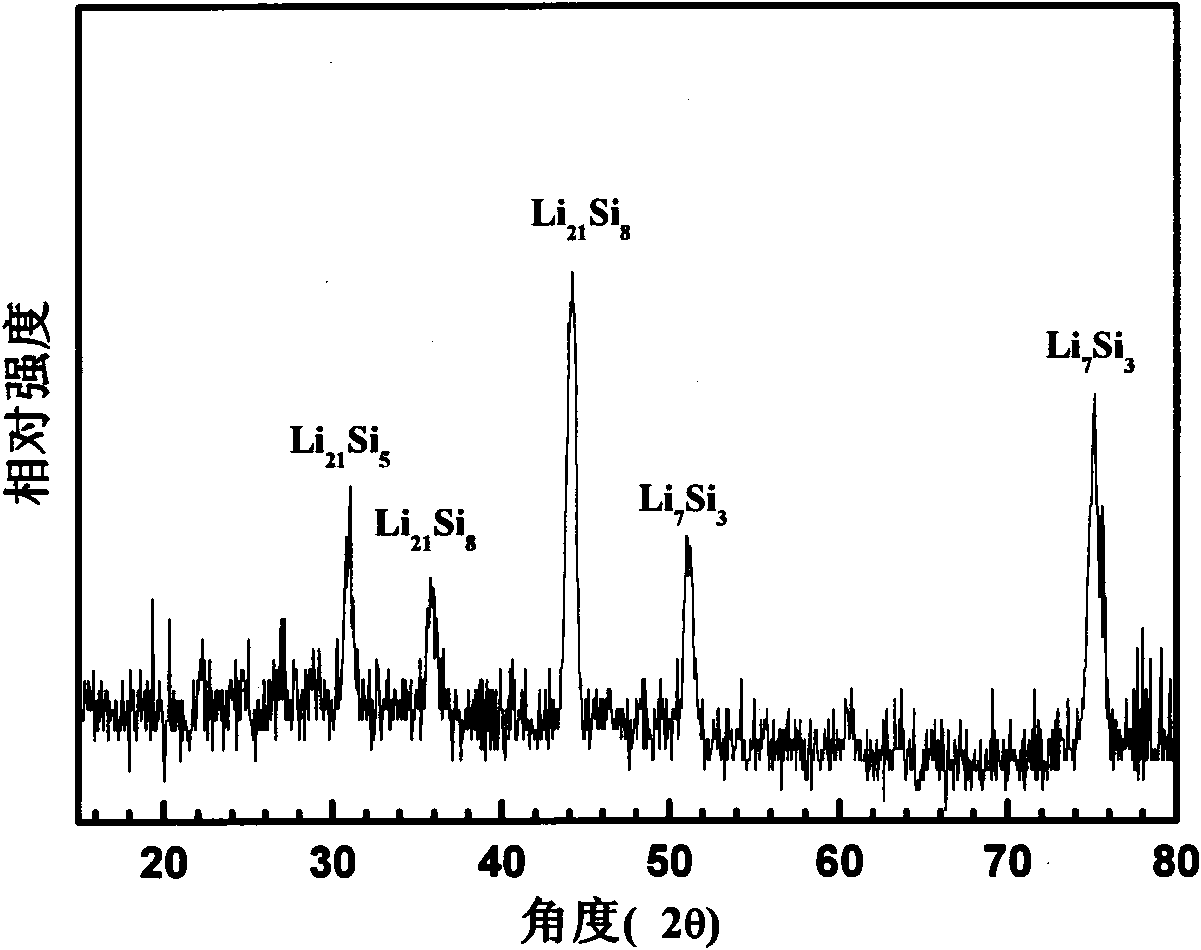
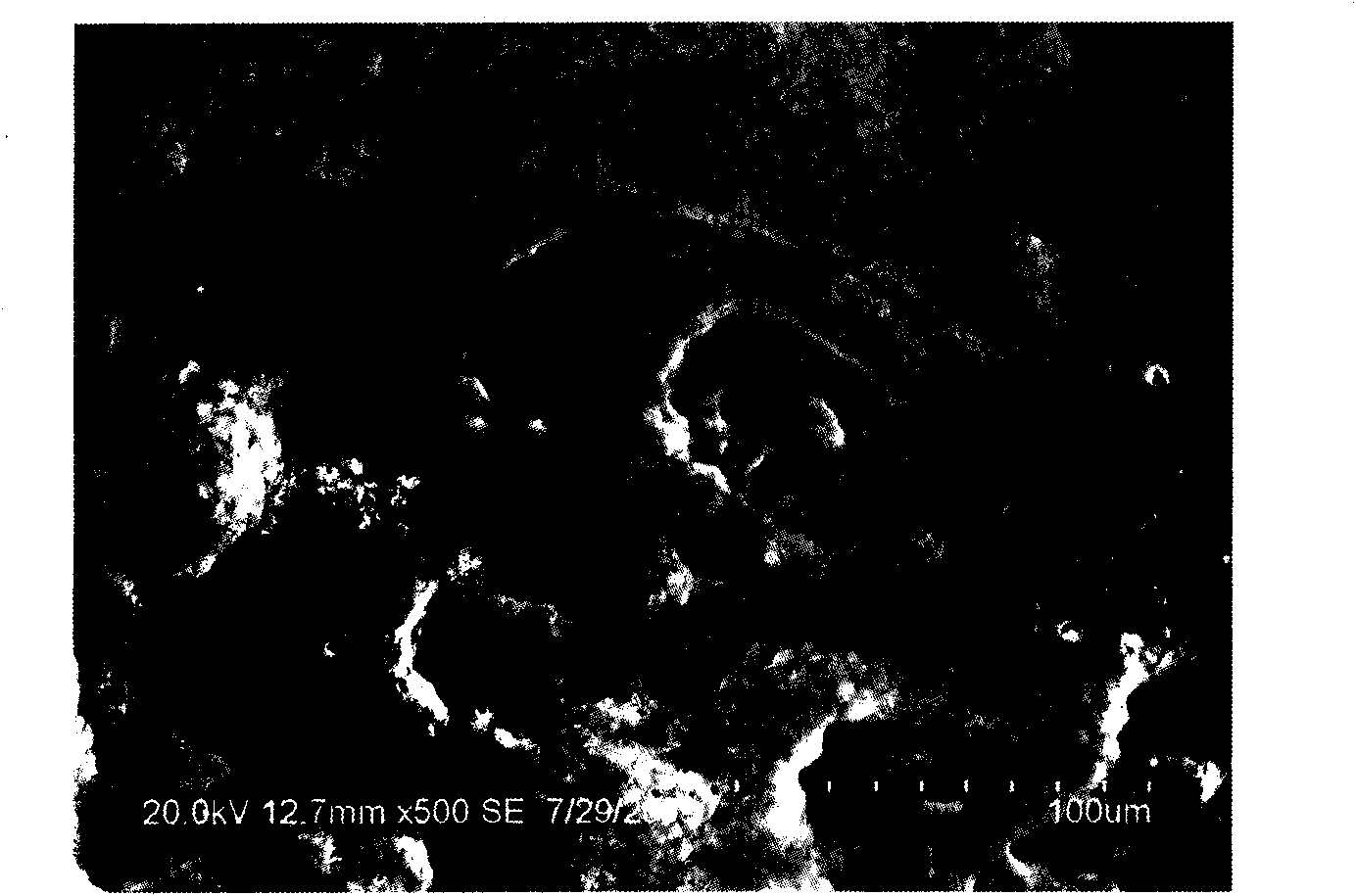
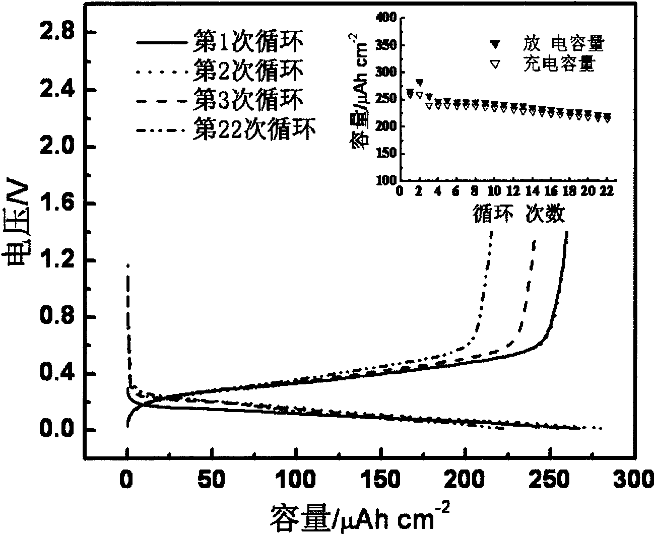
[0029] (1) under argon protection, 1.8618g lithium perchlorate and 1.44ml silicon tetrachloride are joined in the propylene carbonate, stirring and dissolving, obtain 25.0ml electrolytic solution, the molar concentration of silicon tetrachloride in the electrolytic solution is 0.5mol L -1 , the molar concentration of lithium perchlorate is 0.7mol L -1 ;

[0030] (2) Place the above electrolyte in a two-chamber electrolytic cell, and conduct lithium-silicon alloy electrodeposition at 25°C under the protection of argon: the cathode is copper foil with a thickness of 0.02mm; the electrodeposition adopts multi-current step technology , the apparent area current density of the first step is 3.8mA cm -2 , the step time of the first step is 600 seconds, and the apparent area current density of the second step is 1.3mA cm -2 , the step time of the second step is 7200 seconds. After the electrodeposition is completed, the electrodeposited copper foil is rinsed with propylene carbona...

Embodiment 2

[0035] (1) Under the protection of argon, add 1.8988g lithium hexafluorophosphate and 1.44ml silicon tetrachloride to propylene carbonate, stir and dissolve to obtain 25.0ml electrolyte, the molar concentration of silicon tetrachloride in the electrolyte is 0.5mol L -1 , the molar concentration of lithium hexafluorophosphate is 0.5mol L -1 ;

[0036] (2) Place the above electrolyte in a two-chamber electrolytic cell, and conduct lithium-silicon alloy electrodeposition at 30°C under the protection of argon: the cathode is a copper sheet with a thickness of 0.50mm; the electrodeposition adopts multi-current step technology , the apparent area current density of the first step is 3.8mA cm -2 , the step time of the first step is 600 seconds, and the apparent area current density of the second step is 1.3mA cm -2 , the step time of the second step is 7200 seconds. After the electrodeposition is completed, the electrodeposited copper sheet is rinsed with propylene carbonate to obt...

Embodiment 3

[0039] (1) under argon protection, 1.8618g lithium perchlorate and 1.44ml silicon tetrachloride are joined in the propylene carbonate, stirring and dissolving, obtain 25.0ml electrolytic solution, the molar concentration of silicon tetrachloride in the electrolytic solution is 0.5mol L -1 , the molar concentration of lithium perchlorate is 0.7mol L -1 ;

[0040] (2) Place the above electrolyte in a two-chamber electrolytic cell, and conduct lithium-silicon alloy electrodeposition at 25°C under the protection of argon: the cathode is copper foil with a thickness of 0.02mm; the electrodeposition adopts multi-current step technology , the apparent area current density of the first step is 3.8mA cm -2 , the step time of the first step is 600 seconds, and the apparent area current density of the second step is 1.3mA cm -2 , the step time of the second step is 10800 seconds. After the electrodeposition is completed, the electrodeposited copper foil is rinsed with propylene carbon...


PUM

PropertyMeasurementUnit
Thicknessaaaaaaaaaa
Thicknessaaaaaaaaaa
Thicknessaaaaaaaaaa

Abstract

The invention discloses a preparation method of lithium silicon alloy membrane electrode used for lithium ion battery. The lithium silicon alloy membrane electrode used for lithium ion battery is obtained by the steps of adopting electrolytic deposition method and multiple current step technology under argon protection, taking anhydrous organic solvent or ionic liquid containing silicon compound and lithium salt as electrolyte and realizing the co-deposition of silicon and lithium through electrochemical reduction on a metal current collector. By changing the composition of the electrolyte andthe parameters of the multiple current step technology, the cycle capacity and primary cycle efficiency of the lithium silicon alloy membrane electrode can be effectively regulated and controlled. The obtained lithium silicon alloy membrane electrode is used as the negative electrode of a lithium ion battery, the primary cycle efficiency is 45.0 percent -150.0 percent, the charge and discharge capacity is 50.0-1000.0MumAh cm<-2> and the cycle stability is good.

Description

technical field [0001] The invention relates to a preparation method of a battery electrode material, in particular to a preparation method of a lithium-silicon alloy film electrode for a lithium ion battery. Background technique [0002] At present, graphite and modified graphite are widely used as negative electrode materials in commercial lithium-ion batteries, but the theoretical lithium storage capacity is low (graphite is 372mAh g -1 ), prone to organic solvent co-intercalation and other shortcomings, so the research and application of anode materials for high-capacity lithium-ion batteries has become the key to improving battery performance. Among the known lithium storage materials, silicon has the highest theoretical capacity (about 4200mAh g -1 ) and relatively moderate lithium intercalation potential (about 0.1-0.5V vs. Li / Li + ), very suitable as the negative electrode material of lithium ion battery (J.O.Besenhard, J.Yang et.al., J Power Sources, 1997, 68:87)....

Claims


Application Information

Patent Timeline
IPC IPC(8): H01M4/04H01M4/40
CPCY02E60/12Y02E60/10
Inventor 杨军吕荣冠王久林努丽燕娜
Owner SHANGHAI JIAO TONG UNIV
Learn More