
Roast tail gas treatment method in production of catalytic cracking catalyst

A catalytic cracking and treatment method technology, applied in the field of roasting tail gas treatment process, can solve the problems of high investment cost, high waste discharge, no recycling, etc., and achieve the effect of high heat recovery rate, less sewage discharge and simplified process

Inactive Publication Date: 2011-04-06
YUEYANG YITIAN CHEM
View PDF2 Cites 4 Cited by
  • Summary
  • Abstract
  • Description
  • Claims
  • Application Information

AI Technical Summary

Problems solved by technology

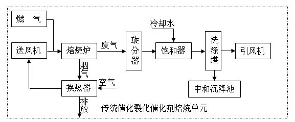
The main problems of this process flow are: (1) Although the flue gas passes through the heat exchanger to recover heat, the efficiency is low, and the flue gas carrying a large amount of heat is directly discharged, and the waste gas generated after the catalytic cracking catalyst is roasted does not return the heat. (2) In the process of treating the exhaust gas generated by catalyst roasting, a large amount of cooling water is required for rapid cooling, resulting in high waste discharge and high energy consumption; (3) In order to overcome the corrosiveness of HCl in the exhaust gas, saturated Hastelloy C-276 material is used for the quenching part of the device, which has good corrosion resistance to low-temperature and medium-temperature hydrochloric acid, and the induced draft fan requires particularly strong resistance to pitting corrosion, acid corrosion, and stress corrosion. Chloride is made of titanium alloy material with excellent corrosion resistance, which is expensive and has high investment cost

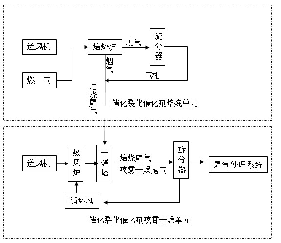
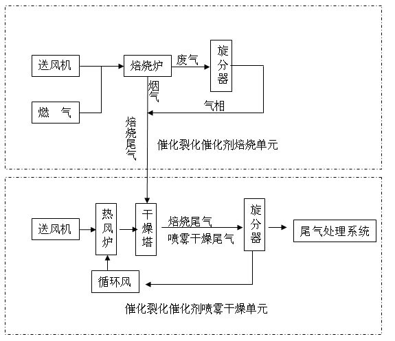
Method used


Image

  • Roast tail gas treatment method in production of catalytic cracking catalyst
  • Roast tail gas treatment method in production of catalytic cracking catalyst
  • Roast tail gas treatment method in production of catalytic cracking catalyst

Examples


Embodiment Construction

[0013] The present invention will be further described below according to accompanying drawing and specific embodiment:

[0014] according to figure 1 In the process shown in the figure, the gas is fully mixed with the air sent by the blower, and is burned in the roaster to produce flue gas above 600°C. At the same time, the catalyst is raised from 130°C to 550°C in the roaster to generate a large amount of waste gas. After the gas and solid are separated by the cyclone, the gas phase and flue gas are directly introduced into the drying tower of the negative pressure system of the cracking catalyst spray drying unit, which is used as the drying heat source. Part of it is used for heat recovery and mixed with catalytic cracking catalyst spray-dried tail gas, and the gas phase is separated by a cyclone and then sent to the tail gas treatment system for treatment. In this way, a high heat recovery rate can be ensured, and the negative pressure of the catalytic cracking catalyst...


PUM


Abstract

The invention mainly relates to a roast tail gas treatment method in the production of the catalytic cracking catalyst. The method comprises the following steps: the roast tail gas is used as a part of the heat source of a drying tower to be introduced in the tower; after the heat exchange, the roast tail gas enters a cyclone separator with the dry tail gas; and the separated gas phase enters a tail gas treatment system for treatment. In the method of the invention, the roast tail gas with a lot of heat which is generated in the roasting process of the catalytic cracking catalyst is directly introduced in the existing catalyst spray drying system for heat recovery, thus the heat recovery rate is high; and the roast tail gas and the dry tail gas of the catalyst spray drying system are treated together, thus the process is simplified and the aims of energy-saving, consumption-reducing, less sewage discharge and investment-saving are achieved.

Description

technical field [0001] The invention belongs to the technical field of catalytic cracking catalyst preparation technology, and mainly relates to the treatment process of roasting tail gas in the catalytic cracking catalyst production process. Background technique [0002] For details on the roasting process in the production of traditional catalytic cracking catalysts, see figure 2 . The flue gas generated by the combustion of gas in the roaster enters the heat exchanger to exchange heat with the cold air and then is discharged into the atmosphere. The heated hot air is sent to the roaster as combustion-supporting air through the blower for heat recovery to achieve the purpose of energy saving. The exhaust gas generated after the catalytic cracking catalyst is roasted is separated from the gas and solid by the cyclone, and the gas phase enters the saturator, and is quenched with cooling water. Into the neutralization settling tank, the gas phase is discharged into the atmo...

Claims


Application Information

Patent Timeline
Patent Type & Authority Applications(China)
IPC IPC(8): B01D53/00B01D45/12
Inventor 廖明球
Owner YUEYANG YITIAN CHEM
Learn More