Supercharge Your Innovation With Domain-Expert AI Agents!

Surface wrapping cutting tool

A cutting tool and surface coating technology, applied in the field of surface coating cutting tools

Active Publication Date: 2015-05-06
MITSUBISHI MATERIALS CORP
View PDF8 Cites 0 Cited by
  • Summary
  • Abstract
  • Description
  • Claims
  • Application Information

AI Technical Summary

Problems solved by technology

[0009] In addition, in the conventional clad tool shown in the above-mentioned Patent Document 2, the (0001) plane of WC and the surface of TiN are formed by physical vapor deposition (PVD) method. The epitaxial interface where the (111) plane is parallel and the [11-20] orientation of WC is parallel to the [110] orientation of TiN can improve the crack resistance and peeling resistance of the hard coating layer during cutting under normal conditions. However, under stricter cutting conditions, such as high-speed heavy cutting of steel or cast iron with high heat generation and high load on the blade, the chipping resistance and peeling resistance of the hard coating layer are not good. Sufficient, so there is a problem of short tool life
In addition, the base material of the above-mentioned existing coated tools requires a special composition containing many plate-shaped WC particles grown on the (0001) plane, so it is actually difficult to apply to hard tools sold in the market without the growth of the (0001) plane. Ordinary tool substrates made of high-quality alloy powder, or small-diameter drills and other fine or complex-shaped tool substrates

Method used


Image

  • Surface wrapping cutting tool
  • Surface wrapping cutting tool
  • Surface wrapping cutting tool

Examples


Embodiment 1

[0089] As raw material powders, WC powder, TiC powder, VC powder, TaC powder, NbC powder, Cr 3 C 2 Powder and Co powder, these raw material powders were mixed into the compounding composition shown in Table 1, wet mixed with a ball mill for 72 hours, dried, and pressed into a green compact with a pressure of 100 MPa. In a vacuum of 6 Pa, a temperature of 1400 ° C The green compact was sintered under the condition of maintaining for 1 hour. After sintering, the blade part was honed with R being 0.03 to form WC-based hard substrates A-1 to A-10 having the blade shape of ISO standard CNMG120408.

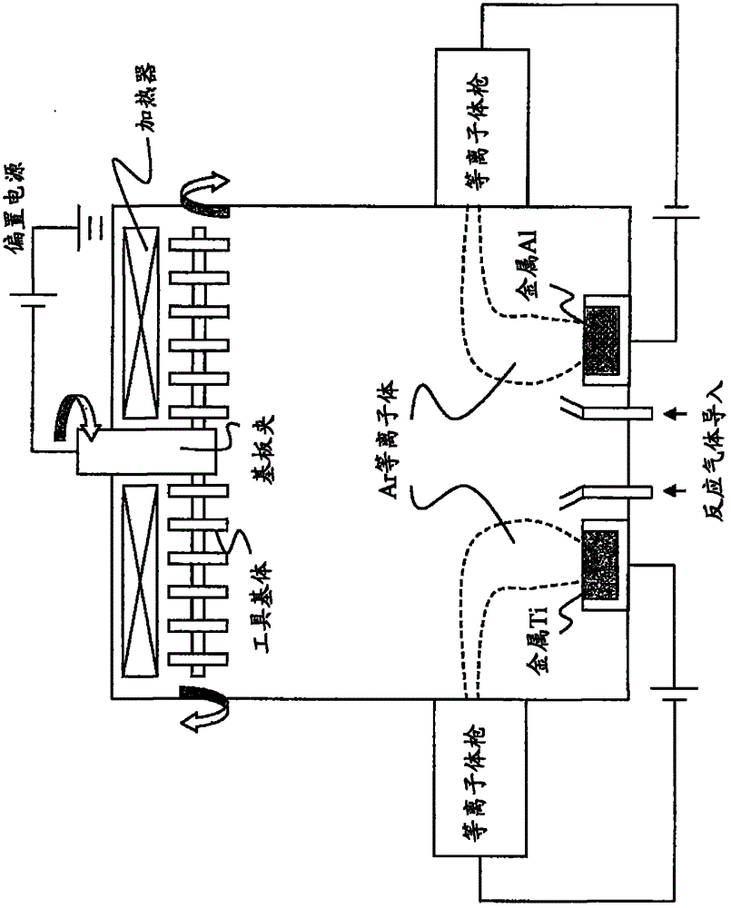
[0090]Next, ultrasonically clean the above-mentioned WC hard substrates A-1 to A-10 in acetone, and in a dry state, install them on figure 1 In the shown ion plating device using a pressure gradient Ar plasma gun, metal Ti and metal Al are installed as evaporation sources. -3 Vacuum below Pa, while introducing Ar gas to become 2.3×10 -2 After Pa, set the discharge power of the press...

Embodiment 2

[0143] As raw material powder, WC powder with an average particle size of 0.2 μm and Cr with an average particle size of 2.3 μm were prepared. 3 C 2 powder, VC powder with an average particle size of 1.5 μm, and Co powder with an average particle size of 1.8 μm. These raw material powders were formulated into the compounding compositions shown in Table 7, and then paraffin wax was added and ball milled in acetone for 24 hours. After drying, the compacts are stamped into various compacts of specified shapes with a pressure of 100 MPa, and these compacts are heated to a specified temperature in the range of 1370-1470 °C at a heating rate of 7 °C / min in a vacuum atmosphere of 6 Pa. After being kept at this temperature for 1 hour, it was sintered under the condition of cooling in the furnace to form a round rod sintered body for tool base formation, and then a groove forming part was manufactured from the round rod sintered body by grinding. The diameter * length was 6 mm * WC-ba...


PUM

PropertyMeasurementUnit
poweraaaaaaaaaa
poweraaaaaaaaaa
thicknessaaaaaaaaaa

Abstract

PROBLEM TO BE SOLVED: To provide a surface coated cutting tool having a heteroepitaxial interface excellent in chipping resistance, peeling resistance and adherence strength of a hard coating layer in small-diameter low-speed cutting or high-speed heavy cutting or the like. SOLUTION: The surface coated cutting tool includes a TiAlN layer of a columnar crystal structure coated and formed by physical vapor deposition on a surface of a WC super-hard base. The tool has, on the interface between the surface of the WC super-hard base and the TiAlN layer, the heteroepitaxial interface which satisfies 1>(X<SB POS="POST">A< / SB>+X<SB POS="POST">C< / SB>) / X≥0.3 (where X refers to a total length of the interface) when the length of an interface of a crystal grain, where [0001]<SB POS="POST">WC< / SB>is parallel to [110]<SB POS="POST">TiAlN< / SB>and [10-10]<SB POS="POST">WC< / SB>is parallel to [001]<SB POS="POST">TiAlN< / SB>, is represented by X<SB POS="POST">A< / SB>, and the length of an interface of a crystal grain, where [0001]<SB POS="POST">WC< / SB>is parallel to [111]<SB POS="POST">TiAlN< / SB>and [11-20]<SB POS="POST">WC< / SB>is parallel to [110]<SB POS="POST">TiAlN< / SB>, is represented by X<SB POS="POST">C< / SB>.

Description

technical field [0001] The present invention relates to a surface-coated cutting tool (hereinafter referred to as a coated tool), which is formed on the surface of a cutting tool substrate made of WC-based cemented carbide by physical vapor deposition to form a hard coating layer comprising at least a TiAlN layer In the surface-coated cutting tool, by forming a heteroepitaxial interface between the surface of the tool substrate and the TiAlN layer, in the small-diameter low-speed cutting that is prone to deposition chipping or the high-speed heavy cutting that applies a high load to the blade, the hard The coating layer exhibits excellent chipping resistance and peeling resistance. Background technique [0002] In general, for the clad tool, there are known inserts that are detachably mounted on the front end of the turning tool in turning of various steels or cast irons, etc. Insert-type end mills that perform cutting in the same way as solid-type end mills, drills that p...

Claims


Application Information

Patent Timeline
Patent Type & Authority Patents(China)
IPC IPC(8): B23B51/00C23C14/24C23C14/06B32B9/00
Inventor 田中耕一高冈秀充
Owner MITSUBISHI MATERIALS CORP
Features
  • R&D
  • Intellectual Property
  • Life Sciences
  • Materials
  • Tech Scout
  • Unparalleled Data Quality
  • Higher Quality Content
  • 60% Fewer Hallucinations
Learn More