Method and device for sewage treatment

A sewage treatment device and technology for sewage treatment, applied in water/sewage multi-stage treatment, oxidized water/sewage treatment, water/sludge/sewage treatment, etc. Examples, not suitable for advanced sewage treatment, etc., to achieve the effect of low excess sludge output, high activated sludge concentration, and low total nitrogen concentration

Inactive Publication Date: 2012-06-13
SHANGHAI GUANGLIAN ENVIRONMENTAL & GEOTECHNICAL ENG CO LTD
View PDF8 Cites 18 Cited by
  • Summary
  • Abstract
  • Description
  • Claims
  • Application Information

AI Technical Summary

Problems solved by technology

[0004] In the 1990s, my country began to develop, research and apply biological aerated filters. In terms of advanced sewage treatment, except for some laboratory research and small-scale research conducted by a few universities and research institutions, there are no large-scale engineering application examples; In the denitrification and ph

Method used


Image

  • Method and device for sewage treatment
  • Method and device for sewage treatment
  • Method and device for sewage treatment

Examples


Embodiment 1

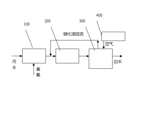
[0033] Such as figure 1 As shown, a method for sewage treatment provided by the present invention includes a step of introducing sewage into an ozone catalytic oxidation tower 100 for catalytic oxidation. The ozone that enters carries out catalytic oxidation treatment to the water body that introduces, also comprises a step that the water discharged from ozone catalytic oxidation tower 100 is introduced into anoxic biological filter 200, in anoxic biological filter 200, utilizes anoxic biological filter 200 The biofilm grown on the surface of the inner porous lightweight filler performs denitrification and denitrification treatment on the injected water, and also includes a step of introducing the treated water from the anoxic biological filter 200 into the aerobic biological filter 300. In the aerobic biological In the filter 300, the biofilm grown on the surface of the porous lightweight filler inside the aerobic biofilter 300 is used to degrade the concentration of organic ...

Embodiment 2

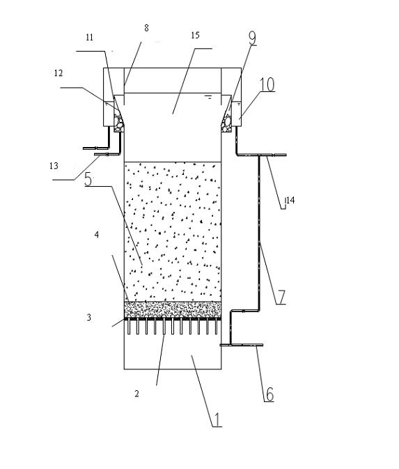
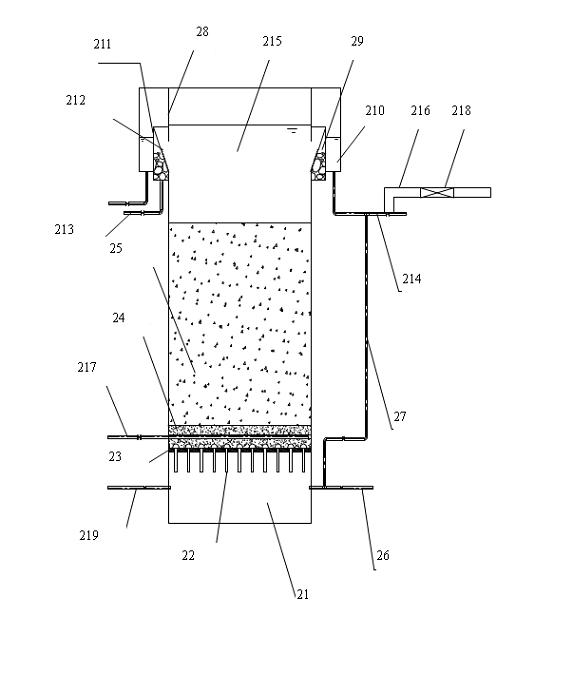
[0041] Such as figure 1 , figure 2 As shown, the present invention also provides a sewage treatment device for realizing the above method, including an ozone catalytic oxidation tower 100, and also includes an anoxic biological filter 200 and an aerobic biological filter 300, and the ozone catalytic oxidation The lower end of the tower 100 is provided with a sewage water inlet, the upper end of the ozone catalytic oxidation tower 100 is provided with a water outlet, and the lower end of the anoxic biological filter 200 is provided with a first water inlet pipe 6, the described The upper end of the anoxic biological filter 200 is provided with a first water outlet pipe 14, and the first water inlet pipe 6 communicates with the water outlet of the ozone catalytic oxidation tower 100, and the aerobic biological filter 300 A second water inlet pipe 26 is arranged at the lower end, and a second water outlet pipe 214 is arranged at the upper end of the aerobic biological filter 30...


PUM


Abstract

The invention relates to a method and a device for sewage treatment, and relates to the field of waste water treatment. The invention aims to improve a denitrification effect of secondary effluent of a sewage treatment plant and reduce operating energy consumption. The method comprises the following steps of: introducing sewage into an ozone catalytic oxidation tower to perform catalytic oxidation; introducing water discharged from the ozone catalytic oxidation tower into an anoxia biofilter; and introducing the water treated by the anoxia biofilter into an aerobic biofilter, wherein the injected water is subjected to the degradation of concentration of organic matters and the nitration of ammonia nitrogen by a biomembrane grown on the surface of a porous light filler inside the aerobic biofilter, so that the concentration of the organic matters in the water reaches an effluent discharge index. The invention also provides a device for realizing the method. The device comprises two biofilters, a high-pressure fan and an ozone catalytic oxidation tower. By the method and the device, denitrification can be realized effectively, and secondary pollution can be avoided.

Description

technical field [0001] The invention relates to the field of chemical industry, and in particular designs a sewage treatment technology, especially a sewage treatment method and device thereof. Background technique [0002] Biological aerated filter, referred to as BAF, is a new sewage treatment process developed on the basis of ordinary biological filtration in the 1980s and early 1990s with reference to the water supply filter process. primary treatment, and later developed to be used directly in secondary treatment. Since the first biological aerated filter sewage treatment plant was built in Europe in the 1980s, biological aerated filters have become popular in developed countries such as Europe, America and Japan. The treatment plant adopts this technology, reflecting the compound and integrated development trend of sewage treatment process. [0003] The biological aerated filter has the functions of removing SS, COD, BOD, nitrification, dechlorination and phosphorus ...

Claims


Application Information

Patent Timeline
IPC IPC(8): C02F9/14C02F3/30C02F1/78
Inventor 方兆昌张彤炬林玉娇何以嘉
Owner SHANGHAI GUANGLIAN ENVIRONMENTAL & GEOTECHNICAL ENG CO LTD
Why Eureka
Try Eureka