Laser-water jet composite micromachining process and device

A microfabrication and water jet technology, applied in metal processing equipment, laser welding equipment, manufacturing tools, etc., can solve the problems of reduced processing quality, crack damage in processing areas, etc., to achieve strong cooling effect, high processing speed, and reduce thermal impact. Effect

Inactive Publication Date: 2012-07-04
SHANDONG UNIV
View PDF6 Cites 26 Cited by
  • Summary
  • Abstract
  • Description
  • Claims
  • Application Information

AI Technical Summary

Problems solved by technology

However, this processing technology inevitably introduces crack damage

Method used


Image

  • Laser-water jet composite micromachining process and device
  • Laser-water jet composite micromachining process and device
  • Laser-water jet composite micromachining process and device

Examples


Embodiment 1

[0025] A single crystal silicon wafer with a thickness of 700 μm was processed, and the material properties are shown in Table 1.

[0026] Table 1 Material properties of monocrystalline silicon wafer

[0027] Density [kg / m 3 ]

Thermal conductivity [W / mK]

Heat capacity[J / kgK]

Thermal diffusivity [m 2 / s]

Melting temperature [K]

2329

130

700

7.974×10 -5

1687

[0028] Processing requirements: the width of the thermal damage zone is less than 20 μm

[0029] According to the material properties, thickness and processing requirements of the processed materials, the laser-water jet composite micromachining process conditions are selected as follows:

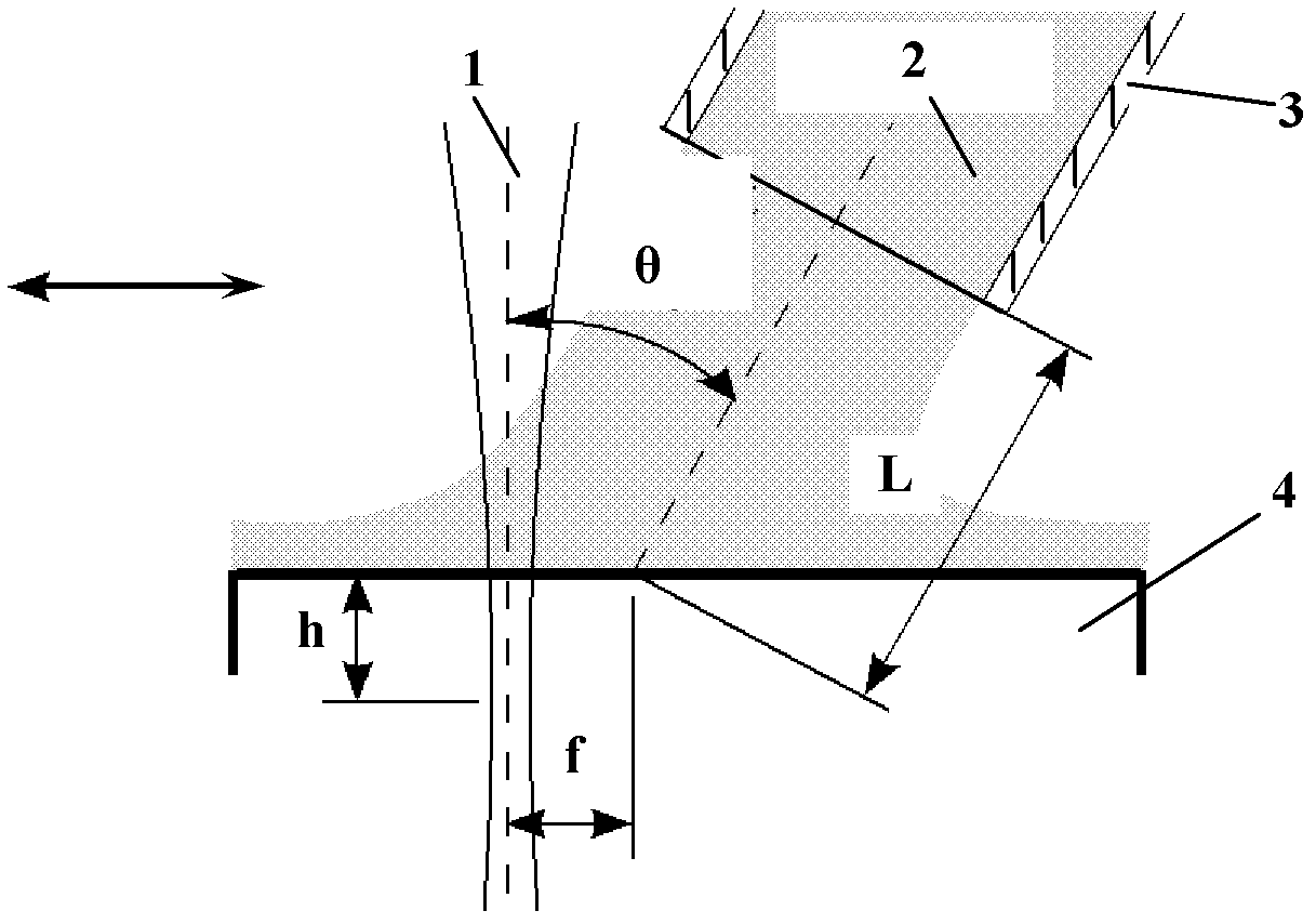
[0030] Water jet offset distance: 0.6mm

[0031] Laser beam focal plane position (fpp): 0mm

[0032] Laser pulse energy: 0.3mJ

[0033] Moving laser pulse overlap factor: 99.3%

[0034] Water jet pressure: 5MPa

[0035] Water jet erosion angle: 30°

[0036] Water ...

Embodiment 2

[0042] A single crystal silicon wafer with a thickness of 700 μm was processed, and the material properties are shown in Table 1.

[0043] Processing requirements: the single-stroke cutting width is greater than 50 μm (the material removal rate is indirectly characterized by the single-stroke cutting width)

[0044] According to the material properties, thickness and processing requirements of the processed materials, the laser-water jet composite micromachining process conditions are selected as follows:

[0045] Water jet offset distance: 0.6mm

[0046] Laser beam focal plane position (fpp): 0mm

[0047] Laser pulse energy: 0.6mJ

[0048] Moving laser pulse overlap factor: 99.9%

[0049] Water jet pressure: 20MPa

[0050] Water jet erosion angle: 60°

[0051] Water jet target distance: 2mm

[0052] Workpiece installation: the monocrystalline silicon wafer workpiece 4 is installed on the two-axis mobile numerical control workbench 13, and the single crystal silicon wafe...


PUM

PropertyMeasurementUnit
The inside diameter ofaaaaaaaaaa
Thicknessaaaaaaaaaa

Abstract

The invention relates to a laser micromachining process and in particular relates to a laser-water jet composite micromachining process and device. The composite micromachining process comprises the following steps of: positioning water jet at the back of a laser beam, leaning the water jet, and simultaneously acting the water jet on the surface of a material, wherein the parameter of a water jet offset distance is as follows: the water jet offset distance, namely the range of the distance between a laser beam action point and post-positioned water jet erosion point, is 0.4-0.8mm; the focal plane position (fpp) parameter of the laser beam is minus 0.6mm-0mm; the energy parameter of laser pulse is 0.3mJ-0.6mJ; the overlap coefficient of mobile laser pulse is 99.3%-99.9%; and the pressure of water jet is 5MPa-20Mpa, and the erosion angle of the water jet is 30-60 degrees. The device provided by the invention is composed of a base body consisting of a horizontal guide rail and a vertical guide rail, a horizontal slide plate, a vertical slide plate, a rotary adjusting support, a water jet unit and a laser cutting unit. According to the invention, the laser heating and softening temperature is far less than the melting or gasifying temperature, the heat influence on a material machining zone is reduced, and high-efficiency, stable and near-nondestructive precise machining is realized.

Description

1. Technical field [0001] The invention relates to a laser micromachining technique, in particular to a laser-water jet composite micromachining technique and a device thereof. 2. Background technology [0002] The laser micromachining system can process various materials such as plastics, glass, ceramics, semiconductor materials and metal films, and the processing accuracy can reach the micron level. Its processing system is widely used in the processing of semiconductor materials and microelectronic devices, biomedical device production, computer manufacturing, electronic communications and other fields. With diameters of a few microns or less and high photon energies, lasers heat, melt and vaporize the material being processed. Therefore, the laser processing technology using this principle is widely used in cutting, micro-hole, etching and other micro-processing technology. However, laser processing also has the defect of thermal damage in the processing area. In orde...

Claims


Application Information

Patent Timeline
IPC IPC(8): B23K26/14B23K26/146
Inventor 黄传真朱洪涛刘增文刘含莲邹斌
Owner SHANDONG UNIV
Why Eureka
Try Eureka