Micro machinery magnetic field sensor and preparation method thereof

A magnetic field sensor and micro-machine technology, applied in the field of magnetic field sensors, can solve the problems of low resonance frequency, complex process, large volume, etc., and achieve the effects of reducing power consumption, simple driving-detecting circuit, and reducing complexity

Active Publication Date: 2012-08-22
SHANGHAI INST OF MICROSYSTEM & INFORMATION TECH CHINESE ACAD OF SCI
View PDF4 Cites 29 Cited by
  • Summary
  • Abstract
  • Description
  • Claims
  • Application Information

AI Technical Summary

Problems solved by technology

[0006] In view of the shortcomings of the prior art described above, the object of the present invention is to provide a micromechanical magnetic field sensor and it

Method used


Image

  • Micro machinery magnetic field sensor and preparation method thereof
  • Micro machinery magnetic field sensor and preparation method thereof
  • Micro machinery magnetic field sensor and preparation method thereof

Examples


Embodiment 1

[0078] Such as Figure 1a to Figure 1k Shown, the present invention provides a kind of preparation method of micromechanical magnetic field sensor, comprises the following steps:

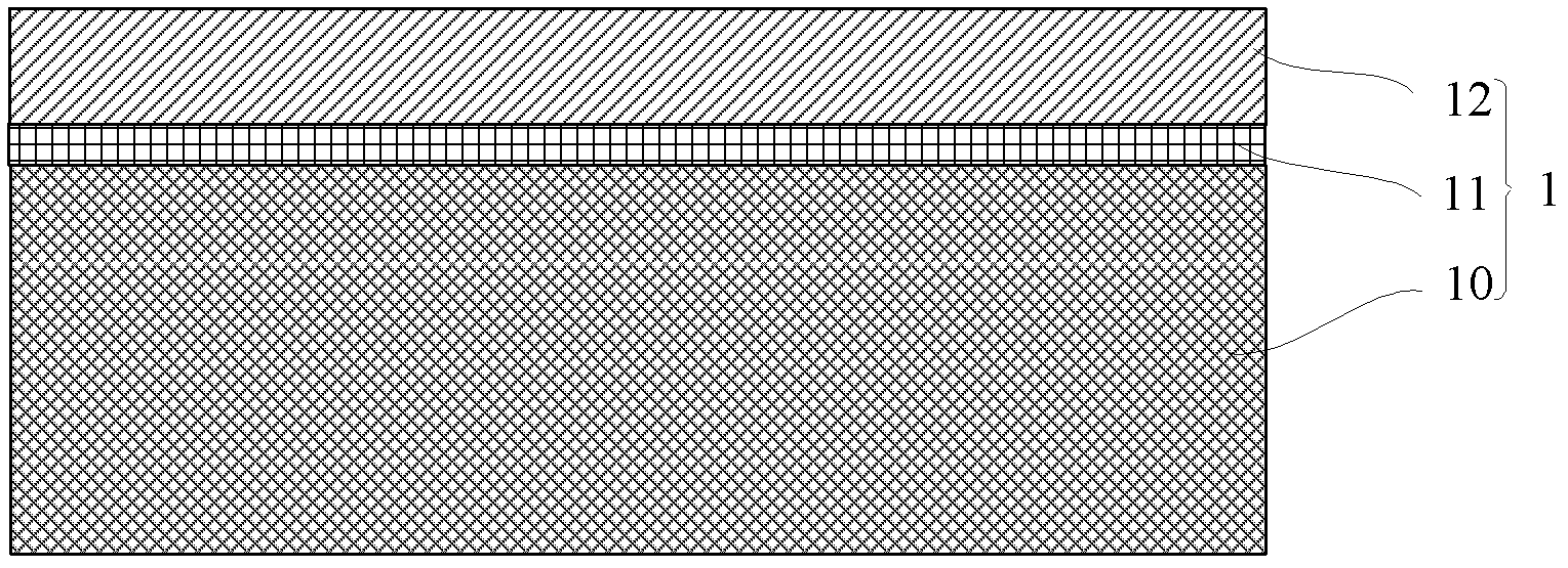
[0079] Step 1): If Figure 1a As shown, an SOI substrate 1 is provided, including substrate silicon 10 , buried oxide layer 11 , and top layer silicon 12 .

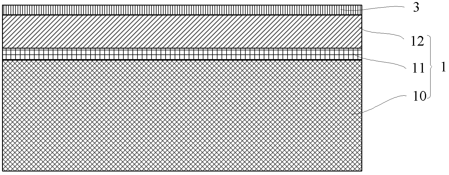
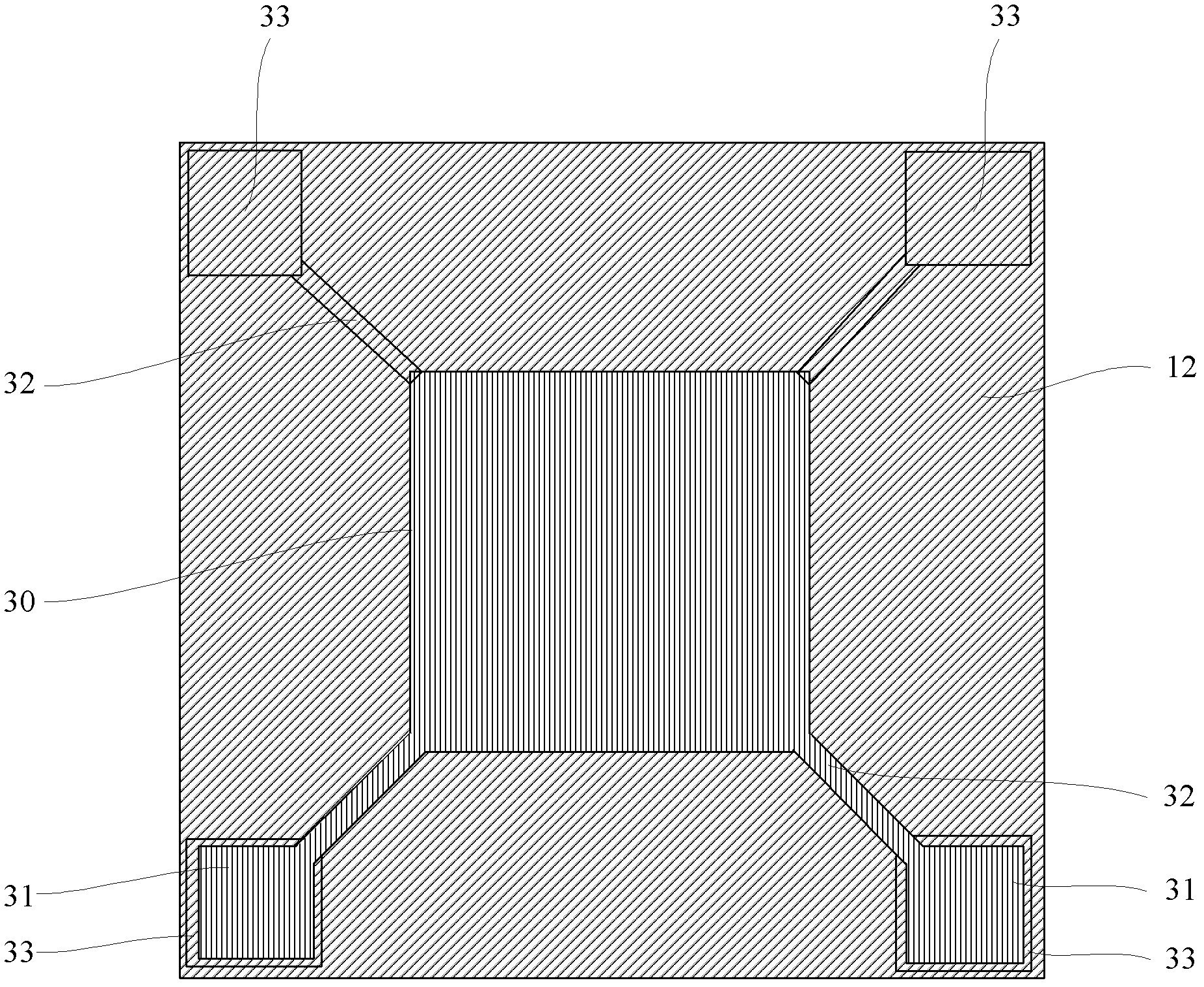
[0080] Step 2): If Figure 1b to Figure 1c As shown, a layer of electrical insulating dielectric layer 3 is deposited by thermal growth or LPCVD on the top layer of silicon of the SOI substrate 1, and the electrical insulating dielectric layer 3 is patterned and etched to retain the corresponding resonator Area 30, the pre-prepared test pad area 31, the pre-prepared support beam area 32, and the pre-prepared electrical insulating medium layer 3 of the anchor point area 33, such as Figure 1c A plan view of the electrically insulating dielectric layer remaining after etching is shown.

[0081] Specifically, the number of the support beam reg...

Embodiment 2

[0093] Such as Figure 2a As shown, an SOI substrate is provided, and a cavity 2 is pre-opened between the top layer silicon 12 and the buried oxide layer 11 of the SOI substrate 1. The formation process of the cavity 2 is well known to those skilled in the art. Conventional process: first, patterned photolithography is performed on the substrate silicon 10, and then a groove (not shown) deep to the buried oxide layer is etched according to the photolithographic pattern. The groove is a square groove, a circular groove The groove, or the annular groove, is preferably a square groove in this embodiment. Then thermally grow a layer of silicon oxide on the bottom of the groove and the peripheral sidewall as the buried oxide layer 11, and finally bond a layer of silicon on the side with the groove as the top layer of silicon 12, the top layer of silicon 12 and The cavity between the buried oxide layers 11 is the cavity 2 .

[0094] The main difference between the process of prep...

Embodiment 3

[0096] Such as Figure 3a to Figure 3l Shown, the present invention provides a kind of preparation method of micromechanical magnetic field sensor, comprises the following steps:

[0097] Step 1): If Figure 3a As shown, an SOI substrate 1 is provided, including substrate silicon 10 , buried oxide layer 11 , and top layer silicon 12 .

[0098] Step 2): If Figure 3b to Figure 3c As shown, a layer of electrical insulating dielectric layer 3 is thermally grown or LPCVD deposited on the top layer of silicon of the SOI substrate 1, and the electrical insulating dielectric layer 3 is patterned and etched to retain the corresponding pre-prepared The resonator area 30, the pre-prepared test pad area 31, the pre-prepared support beam area 32, and the pre-prepared electrical insulating medium layer 3 of the anchor point area 33, such as Figure 3c Shown is a schematic plan view after etching the electrical insulating dielectric layer 3 .

[0099] Specifically, the number of the sup...


PUM


Abstract

The invention provides a micro machinery magnetic field sensor and a preparation method thereof, which belong to the field of a micro electro mechanical system. A sacrifice layer with a contact hole is deposited on a structural layer of a device, a metal coil is prepared on the sacrifice layer, then the sacrifice layer is corroded, and finally dry etching is used to manufacture a device structure, and the device structure is released to form a resonance oscillator so as to form the metal coil to hang on the micro machinery magnetic field sensor above the resonance oscillator. The resonance oscillator of the micro machinery magnetic field sensor works in an extension module, so that induced electromotive force produced by each small section of metal cutting magnetic induction lines on the metal coil can be overlapped, strength of output signals is strengthened, and contact surface between the metal coil and the resonance oscillator is reduced to solve the problem of signal crosstalk in high frequency. In addition, the micro machinery magnetic field sensor has the advantages of being low in power consumption, simple in driving-detection circuit, small in temperature influence, simple in process and the like.

Description

technical field [0001] The invention relates to a magnetic field sensor, in particular to a micromechanical magnetic field sensor and a preparation method thereof, and belongs to the field of micromechanical magnetic field sensor design and micromachining. Background technique [0002] By sensing the earth's magnetic field to identify directions or navigate ships, especially in the fields of navigation, aerospace, automation control, military and consumer electronics, magnetic field sensors are more and more widely used. Magnetic field sensing technology is developing towards the direction of miniaturization, low power consumption, high sensitivity, high resolution and compatibility with electronic equipment. According to the working principle, the magnetic field sensor can be divided into: superconducting quantum interference magnetic field sensor, Hall magnetic field sensor, fluxgate magnetometer, giant magnetoresistive magnetic field sensor and induction coil magnetic fie...

Claims


Application Information

Patent Timeline
IPC IPC(8): G01R3/00G01R33/028B81C1/00
Inventor 熊斌吴国强徐德辉王跃林
Owner SHANGHAI INST OF MICROSYSTEM & INFORMATION TECH CHINESE ACAD OF SCI
Why Eureka
Try Eureka