Apparatus and method for continuously preparing thin-layer grapheme or hybrid combining thin-layer grapheme with thin-walled carbon nanotube

A thin-layer graphene and carbon nanotube technology, which is used in the preparation of thin-layer graphene or thin-layer graphene and thin-walled carbon nanotube hybrids, and the preparation of thin-layer graphene or thin-layer graphene and thin-walled carbon nanotubes. In the field of pipe hybrid devices, it can solve the problems of high cost, high price and long residence time, and achieve the effects of simple installation support, wide application range and low equipment cost.

Inactive Publication Date: 2012-10-17
TSINGHUA UNIV
View PDF2 Cites 14 Cited by
  • Summary
  • Abstract
  • Description
  • Claims
  • Application Information

AI Technical Summary

Problems solved by technology

[0003] At present, the process of preparing thin-layer graphene or hybrids of thin-layer graphene and thin-walled carbon nanotubes is mainly carried out in fixed-bed reactors or fluidized-bed reactors with gas-solid flow upward. If the residence time in the container is too long, it is easy to produce multilayer graphene (>10 layers), multi-walled carbon nanotubes with large diameter (number of walls>5), and impurities such as amorphous carbon and carbon-coated metal nanoparticles, so The purification process of the product is complex and expensive
Large-area thin-layer graphene can be deposited using a drum reactor, but its hybrids with thin-walled carbon nanotubes cannot be prepared
At the same time, large-area thin-layer graphene is mainly used in the fields of nano-circuits or transparent conductive displays, but the prepara

Method used


Image

  • Apparatus and method for continuously preparing thin-layer grapheme or hybrid combining thin-layer grapheme with thin-walled carbon nanotube
  • Apparatus and method for continuously preparing thin-layer grapheme or hybrid combining thin-layer grapheme with thin-walled carbon nanotube

Examples


Embodiment 1

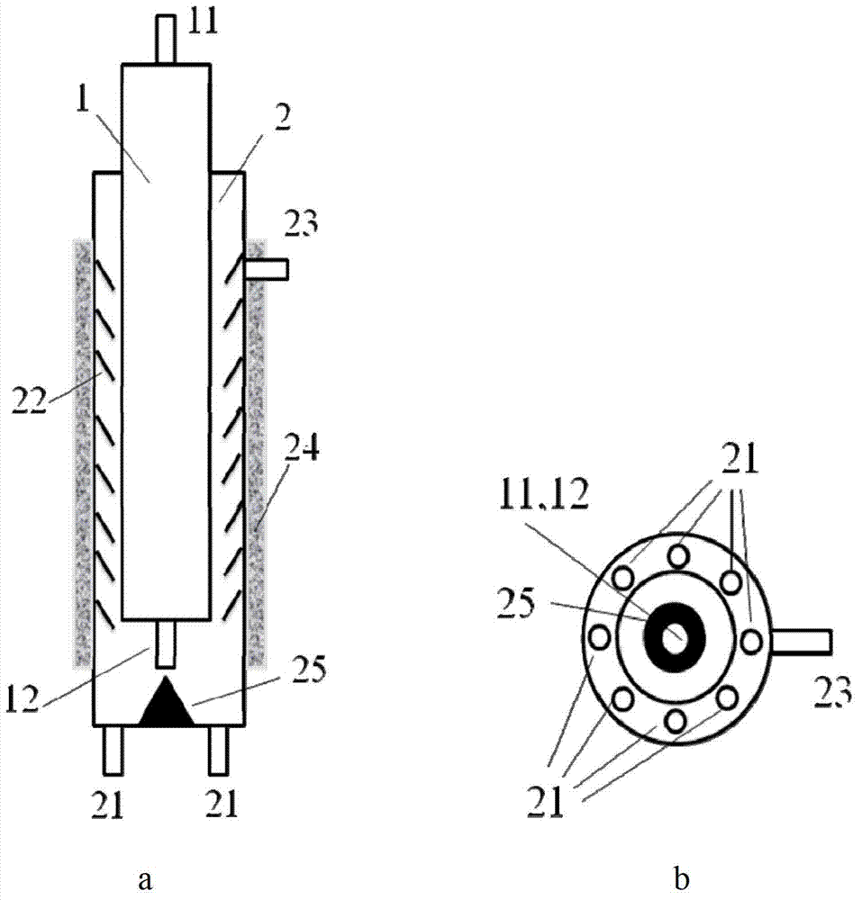
[0055] use as figure 1 The reaction device shown, wherein the ratio of the cross-sectional area of ​​the down-bed 1 to the riser 2 is 3:1, uses Fe / MgO catalyst (the mass ratio of Fe is 1.2%, the rest is MgO, the particle size is 100 microns, and the bulk density is 1600 kg / m 3 ), the reaction gas is a mixture of methane, hydrogen, argon and nitrogen (the volume ratio of methane: hydrogen: argon: nitrogen is 2:7:300:100), and the total space velocity of carbon source is 300 g / gcat / h; Pass the reaction gas and catalyst into the down-bed 1, and generate a hybrid of single-layer graphene and single-walled carbon nanotubes at 800°C and a gas velocity of 0.1m / s; when the gas-solid mixture from the down-bed When the gas-solid mixture flowing out of the outlet 12 enters the bottom of the riser 2, methane is replenished through the gas inlet 21 of the riser, so that the volume ratio of methane:hydrogen remains at 2:7; at 800°C, the gas velocity is 1~1.5m / s Under certain conditions, p...

Embodiment 2

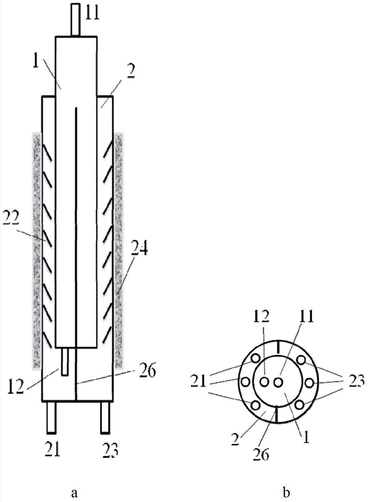
[0057] use as figure 2 The reaction device shown, wherein the ratio of the cross-sectional area of ​​the down-bed 1 to the riser 2 is 1.2:1, using Ni / Mo / SiO 2 Catalyst (Ni mass proportion is 1%, Mo mass proportion is 0.5%, the rest is SiO 2 , with a particle size of 400 microns and a bulk density of 500 kg / m 3 ), the reaction gas is a mixture of acetylene, ethylene, and hydrogen (the volume ratio of acetylene: ethylene: hydrogen is 2:2:4), and the total space velocity of the carbon source is 20g / gcat / h; the reaction gas and the catalyst are passed down In bed 1, hybrids of graphene and carbon nanotubes are generated under the conditions of 450°C and gas velocity of 2m / s; , replenish acetylene and ethylene through the gas inlet 21 of the riser, so that the volume ratio of acetylene:ethylene:hydrogen remains at 2:2:4. The component area 22 at the inlet 21 end reaches the top of the riser 2, moves downward after passing through the top of the vertical partition 26, and then p...

Embodiment 3

[0059] use as figure 1 The reaction device shown, wherein the ratio of the cross-sectional area of ​​the down-bed 1 to the riser 2 is 4:1, Fe / V / Al 2 o 3 Catalyst (the mass proportion of Fe is 1%, the mass proportion of V is 0.2%, and the rest is Al 2 o 3 , with a particle size of 500 nm and a bulk density of 500 kg / m 3 ), the reaction gas is a mixture of ethanol, methanol, and hydrogen (the volume ratio of ethanol:methanol:hydrogen is 2:0.5:500), and the total space velocity of the carbon source is 50 g / gcat / h; the reaction gas and the catalyst are passed into The down-bed 1 generates thin-walled carbon nanotubes at 900°C and the gas velocity is 1m / s; when the gas-solid mixture flowing out from the outlet 12 of the down-bed gas-solid mixture enters the bottom of the riser 2, it passes through the riser The gas inlet 21 of the riser of 2 is supplemented with ethanol and methanol, so that the volume ratio of acetylene: ethylene: hydrogen is still maintained at 2:0.5:500. At ...


PUM

PropertyMeasurementUnit
Bulk densityaaaaaaaaaa

Abstract

The invention discloses an apparatus for continuously preparing thin-layer grapheme or a hybrid combining the thin-layer grapheme with thin-walled carbon nanotube and a preparation method of the thin-layer grapheme or the hybrid combining the thin-layer grapheme with the thin-walled carbon nanotube by utilizing the apparatus, which belongs to the field of multiphase flow reactor technology and carbon nanomaterial preparation. The apparatus provided by the invention comprises a downer, a riser and a heating system wrapped on the outside of the riser for heating up. According to the method, the heating system is started; reaction gas and a template are led through the entrance of a gas-solid mixture of the downer to grow thin-layer grapheme, or the reaction gas and a catalyst are led to grow hybrid of thin-layer grapheme and thin-walled carbon nanotube; and then the reaction gas is led through the a gas inlet of the riser; all gas-solid mixture moves forward, passes through a member area, gets out of the riser and enters a subsequent gas-solid separation section and a cooling and storage section. The apparatus provided by the invention has the advantages of simplicity in structure and low cost of equipment. The method provided by the invention has low environmental pollution and the obtained product has high quality.

Description

technical field [0001] The invention belongs to the field of multiphase flow reactor technology and carbon nanomaterial preparation, and specifically relates to a device for preparing thin-layer graphene or a hybrid of thin-layer graphene and thin-walled carbon nanotubes and using the device to prepare thin-layer graphene Or the method of thin-layer graphene and thin-walled carbon nanotube hybrids. Background technique [0002] Thin-layer graphene (1-10 layers) or hybrid of thin-layer graphene and thin-walled carbon nanotubes (1-3 walls, mostly 0.6-4 nm in diameter, hundreds of microns or even tens of centimeters in length) It has good electrical conductivity, thermal conductivity, mechanical properties and huge specific surface area, and can be widely used in the reinforcement of polymers, conductive materials, field emission materials, wave-absorbing or electromagnetic shielding materials, catalyst carriers, nano-circuits, electrical Chemical energy storage and other fiel...

Claims


Application Information

Patent Timeline
IPC IPC(8): C01B31/04C01B31/02B82Y30/00C01B32/162C01B32/184
Inventor 骞伟中崔超婕郑超余云涛孔垂岩魏飞
Owner TSINGHUA UNIV
Why Eureka
Try Eureka