Dye-sensitized solar cell, and seal member to be used for the dye-sensitized solar cell

A solar cell and dye-sensitized technology, which is applied in the field of dye-sensitized solar cells, can solve the problems of adverse effects of dye-sensitized solar cell structure and difficult proposals, and achieve high durability, high reliability, and high viscosity. Relay effect

Inactive Publication Date: 2012-10-17
NITTO DENKO CORP
View PDF7 Cites 16 Cited by
  • Summary
  • Abstract
  • Description
  • Claims
  • Application Information

AI Technical Summary

Problems solved by technology

[0004] However, it is difficult to say that there is a sufficiently satisfactory proposal for a sealing method and a sealing material that are rich in the above-mentioned durability for preventing electrolyte solution leakage.
On the other hand, as the sealing material, epoxy resin-based sealing materials, urethane resin-based sealing materials, and photocurable acrylic sealing materials conventionally known as liquid crystal sealing materials are used. These sealing materials have the following problems: due to their polarity structure, swelling caused by the electrolyte solution occurs, and as a result, the structure of the dye-sensitized solar cell is adversely affected

Method used


Image

  • Dye-sensitized solar cell, and seal member to be used for the dye-sensitized solar cell
  • Dye-sensitized solar cell, and seal member to be used for the dye-sensitized solar cell
  • Dye-sensitized solar cell, and seal member to be used for the dye-sensitized solar cell

Examples


Embodiment 1

[0195] Materials shown in the following (I) to (II) were prepared and assembled as shown in (III).

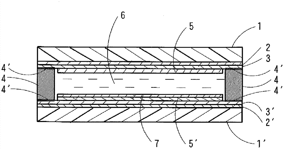
[0196] (I) Fabrication of working electrode side substrate and counter electrode side substrate

[0197] (I-a) Fabrication of a working electrode side substrate with a surface coating treatment using a specific silane coupling agent

[0198] After forming a SiOCN layer on a resin substrate [made of polyethylene naphthalate (PEN), size: 76 mm x 52 mm x thickness 125 μm] by plasma-assisted evaporation, the surface is oxidized to form SiO 2 layer, thereby forming an inorganic layer with a two-layer structure. That is, as a result, a SiOCN layer comprising a thickness of about 250 nm and a SiO layer of about 40 nm in thickness are formed. 2 The inorganic layer of the 2-layer structure of the layer. Then, on the above inorganic layer (SiO 2layer) surface to form an ITO transparent conductive electrode layer, and then form a porous titanium oxide semiconductor layer that adsorbs ...

Embodiment 2

[0206] As a silane coupling agent, on the inorganic layer (SiO 2 layer) part, instead of the methanol solution of 1 wt% 3-acryloxypropyltrimethoxysilane above, a 1 wt% methanol solution of 3-methacryloxypropyltrimethoxysilane was applied. Except for this, the dye-sensitized solar cell was assembled in the same manner as in Example 1.

Embodiment 3

[0208] Instead of the photopolymerizable composition (A) of the above-mentioned Example 1, 7 g of the above-mentioned hydrogenated elastomer derivative a and 3 g of dimethylol dicyclopentane diacrylate (tricyclodecane dimethanol diacrylate) were used. , and a photopolymerizable composition (A) of 0.5 g of a photoradical polymerization initiator. Except for this, the dye-sensitized solar cell was assembled in the same manner as in Example 1.


PUM


Abstract

A dye-sensitized solar cell of a polymer resin type is provided, which is excellent in sealability. A counter electrode substrate (1) provided with an electrically conductive transparent electrode layer (5) and a working electrode substrate (1') provided with an electrically conductive transparent electrode layer (5') are opposed to each other with the electrode layers (5, 5') facing inward. A space defined between the substrates (1, 1') is sealed with a seal member (4) disposed along peripheries of inner surfaces of the substrates (1, 1'). An electrolyte solution is filled in the sealed space. The substrates (1, 1') are each made of a polymer resin material. Inorganic layers (2, 2' , 3, 3') are provided between the substrates (1, 1') and the electrode layers (5, 5'). The seal member (4) is composed of a material obtained by curing a photopolymerizable composition essentially comprising a specific hydrogenated elastomer derivative. The inorganic layers (3,3') each have a portion coated with a (meth)acryloxyalkylsilane silage coupling agent in contact with the seal member (4).

Description

technical field [0001] The present invention relates to a polymer resin (plastic film) substrate-type dye-sensitized solar cell in which a pair of electrode substrates face each other, are bonded and sealed, and an electrolyte solution is enclosed. A dye-sensitized solar cell with high sealing properties and excellent durability, and a sealing material therefor. Background technique [0002] On titanium oxide (TiO) loaded with dye 2 A dye-sensitized solar cell obtained by enclosing a redox electrolyte solution between a transparent conductive substrate of a porous semiconductor film such as ) and an opposing electrode substrate is expected to be a next-generation inexpensive solar cell due to its high conversion efficiency of sunlight. [0003] However, when a redox-based electrolyte solution such as iodine or lithium iodide is sealed in a polymer resin (plastic film) substrate, if the conventionally used ethylene-methacrylic acid copolymer ionomer resin is used as the seal...

Claims


Application Information

Patent Timeline
Patent Type & Authority Applications(China)
IPC IPC(8): H01G9/004H01G9/04H01G9/08H01G9/20
CPCH01G9/2095H01G9/2059Y02E10/542H01G9/2077H01G9/2031Y02P70/50C08L101/02H01L31/048
Inventor 五十岚一雅长谷川由纪吉田直子山田泰美佐佐和明
Owner NITTO DENKO CORP
Why Eureka
Try Eureka