Solid heat storage structure and processing method

A processing method and solid technology, applied in solar heat storage, chemical instruments and methods, heat storage equipment, etc., can solve the problems of inability to form self-support, large heat loss in heat preservation cycle, affecting heat storage capacity, etc., and achieve a good overall exchange rate. Thermal performance, good interfacial heat transfer performance, and the effect of improving bonding and welding performance

Inactive Publication Date: 2012-10-24
BEIJING POWERTECH
View PDF4 Cites 10 Cited by
  • Summary
  • Abstract
  • Description
  • Claims
  • Application Information

AI Technical Summary

Problems solved by technology

In recent years, it has been reported that a composite phase change material (shape-fixed phase change material) supported by a specific material as a matrix has been obtained in the laboratory to store heat, but it has the disadvantage of low thermal conductivity, and the phase change material occurs during the heat storage process. Phase change, due to the change in volume, it is prone to hidden dangers of leakage
In addition, ternary aluminum alloys are also used in industry as phase change storage materials. Multiple cycles have negative effects on heat storage performance, such as the temperature and life of phase change heat storage, because the heat storage material itself is in the working process. Repeated solid-liquid phase transitions in the environment, impurity elements will affect its performance and service life
At present, the existing industrialized solar thermal power generation units mostly use inorganic salts as heat storage materials, but inorganic salts have the disadva

Method used


Image

  • Solid heat storage structure and processing method
  • Solid heat storage structure and processing method
  • Solid heat storage structure and processing method

Examples


Embodiment Construction

[0038] The present invention will be further described in detail below in conjunction with the examples.

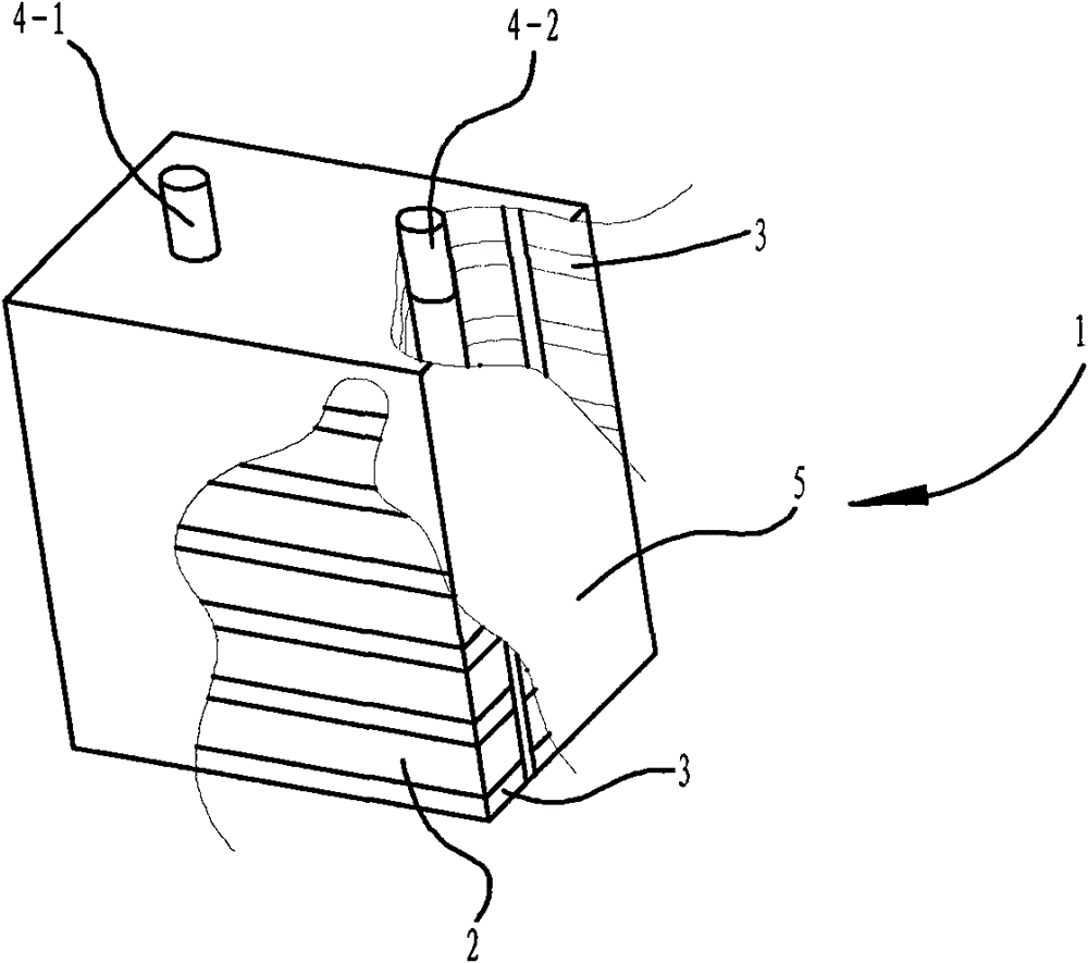
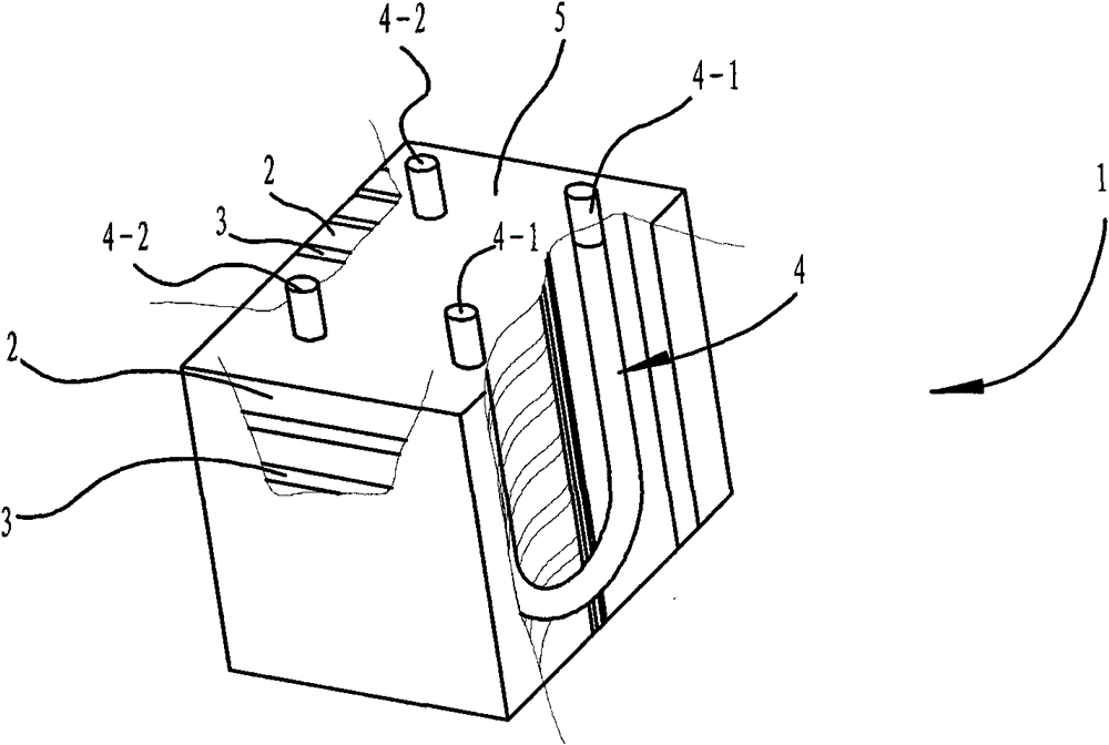
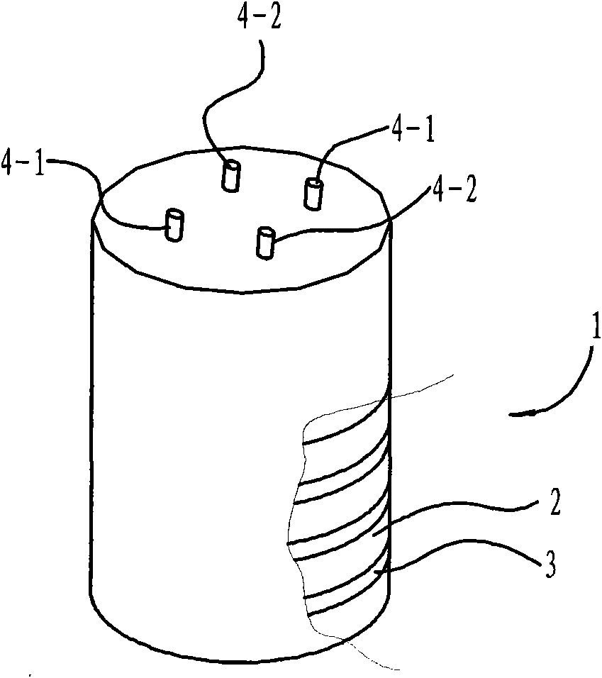
[0039] figure 1 , figure 2 and image 3 It is a schematic diagram of a structural embodiment of the overall structure of the solid heat storage structure 1 of the present invention at different application temperatures. As shown in the figure, the solid heat storage structure 1 is formed by stacking a plurality of regular-shaped solid heat storage blocks 2, preferably solid heat storage blocks 2 of one or more shapes or sizes, specifically including solid heat storage blocks 2 and A high thermal conductivity bonded filling material 3; a solid heat storage structure 1 with high thermal conductivity and heat storage formed integrally by the two. A heat exchange pipe 4 is arranged inside the solid heat storage structure 1, preferably a metal heat exchange pipe 4, and the high thermal conductivity adhesive filling material 3 is in close and good contact with the heat exch...


PUM


Abstract

The invention provides a solid heat storage structure and a processing method. The solid heat storage structure is a self-supported three-dimensional through layered or network structure formed by a solid heat storage block of a regular shape and a bonding filling material with high heat conductivity; and a high-heat-conductivity metal sheet in the bonding filling material is molten into a liquid for permeating into gaps of the solid heat storage block at certain temperature, or only a bonding agent is used for melting or bonding the solid heat storage block, and is solidified or welded or bonded and cured into an entire heat storage solid structure block together with the solid heat storage block after being cooled. A solid heat storage medium is used for storing heat by using the sensible heat performance of a solid, runs safely, is easy for processing, and is low in cost; three-dimensional netlike structures made of a high-heat-conductivity material are uniformly distributed in an entire heat storage medium space, so that the transfer of heat energy is enhanced greatly, and the entire medium has high heat conductivity; and the solid heat storage structure has high heat conductivity and high thermal capacity, and can be applied to various heat storage applications, in particular to solar energy light heat utilization systems.

Description

technical field [0001] The invention relates to a heat storage device, in particular to a heat storage device in a solar photothermal utilization system. Background technique [0002] Solar energy is an ideal clean energy source, but there is a problem of timeliness in utilization. The energy received during the sunshine period is more than required, but it cannot function after sunset. Therefore, how to store the excess energy during sunshine for the continuous operation of the system after sunset, that is, to take the excess to make up for the deficiency, has become a key issue in realizing the continuous operation of the solar thermal utilization device. [0003] In the existing solar energy storage technologies, various heat storage media have been reported or used. In recent years, it has been reported that a composite phase change material (shape-fixed phase change material) supported by a specific material as a matrix has been obtained in the laboratory to store heat...

Claims


Application Information

Patent Timeline
IPC IPC(8): F28D20/00F24J2/34F24J2/50C09K5/14
CPCF24J2/50F24J2/34F28D20/0056Y02E10/40F28F2013/006Y02E70/30F28F2275/02F28F2255/06F28F2275/06C09K5/14F28D20/00Y02E60/142F24S60/00Y02E60/14
Inventor 刘阳
Owner BEIJING POWERTECH
Why Eureka
Try Eureka