Fuel gas injection type recovery method of sensible heat of convertor coal gas and convertor flue gas

A converter gas and converter flue gas technology, which is applied to furnaces, furnace components, waste heat treatment, etc., can solve the problems of large initial investment, high operating costs, high maintenance costs, waste, etc., to reduce initial investment and operating costs, and reduce operating costs High, avoid water consumption effect

Active Publication Date: 2012-12-19
SHANDONG PROVINCE METALLURGICAL ENG CO LTD
View PDF7 Cites 5 Cited by
  • Summary
  • Abstract
  • Description
  • Claims
  • Application Information

AI Technical Summary

Problems solved by technology

[0004] 1. The physical sensible heat in the converter flue gas is all wasted in the process of vaporization and cooling. Due to the large amount of flue gas in the converter, this waste is amazing
[0005] 2. In the evaporative cooling tower, the cooling rate of the pre-cooled converter flue gas from the flue heat exchange device is very fast, which has the condition that the reaction between oxygen and gas is not sufficient, and there is a chance of coexistence of remaining oxygen and remaining gas , become an important safety hazard; when the amount of oxygen and gas are in a transitional state where they can be basically exhausted through combustion, their concentrations are relatively low at this time, and the cooling rate in the vaporization cooling tower is very fast Faster, it is easier to exist the coexistence state of residual oxygen and residual gas, so that the existence of safety isolation section with low concentration of oxygen and combustible gas between the gas flow section with excess oxygen and excess gas is not obvious, which also constitutes an important safety hazard
At the same time, when the above-mentioned gas flow section enters the switching station, it will cause the gas concentration to be still high, such as about 35%, because the oxygen content exceeds the standard, such as ≥ 2%, and it will be released, thereby causing the gas. waste
[0006] 3. Due to the dangerous concentration of oxygen entering the fine dust collector and the subsequent system is unavoidable, there are potential safety hazards in the system
[0007] 4. Evaporation cooling not only wastes a lot of sensible heat of the converter flue gas, but also consumes a lot of water, and the quality of the converter gas is also reduced due to the entry of water, which improves the anti-corrosion requirements of the system
[0008] 5. Because the moisture entering the system has a tendency to condense, the bag filter cannot be used in the existing system; the use of the electrostatic precipitator not only requires a large initial investment, but also high operating costs (including maintenance costs and energy consumption, etc.)

Method used


Image

  • Fuel gas injection type recovery method of sensible heat of convertor coal gas and convertor flue gas
  • Fuel gas injection type recovery method of sensible heat of convertor coal gas and convertor flue gas

Examples


Embodiment 1

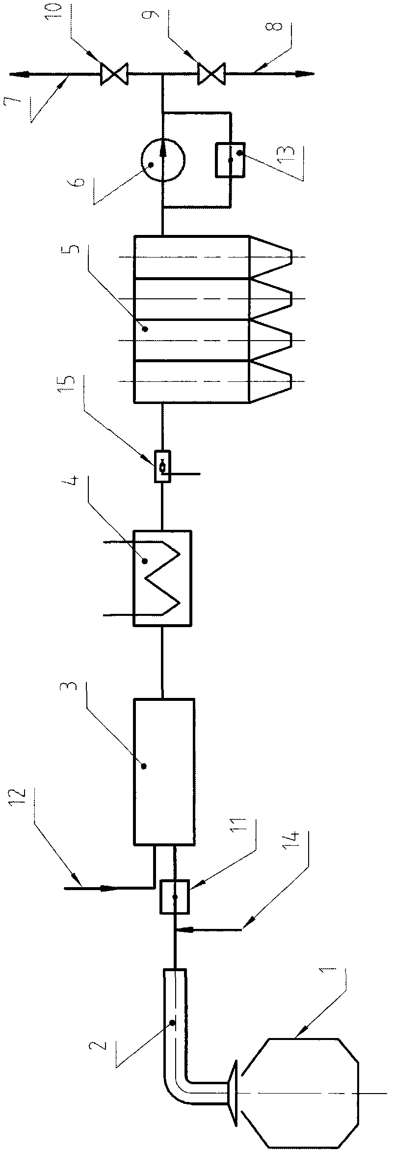
[0038] Example 1, such as figure 1 shown.

[0039] exist figure 1Among them, 1 is the converter. 2 is the flue heat exchange device of the converter. 3 is a combined device that is integrated and has the functions of rough dust removal, heat storage and combustion chamber. 4 is a heat exchange device. 5 is a fine dust removal device, specifically, it is a bag filter. 6 is blower fan. 7 is a recovery channel for converter gas. 8 is the combustion release channel of the converter gas, so as to facilitate emergency and / or release residual gas that does not have recovery value. 9 and 10 are control valves arranged on the release passage 8 and the recovery passage 7 respectively. 11 is an on-off valve installed between the combined device 3 and the flue heat exchange device 2. It is not difficult to see that the on-off valve 11 also conforms to the characteristics of being arranged before the combustion chamber or the regenerative combustion chamber, because in this embod...

Embodiment 2

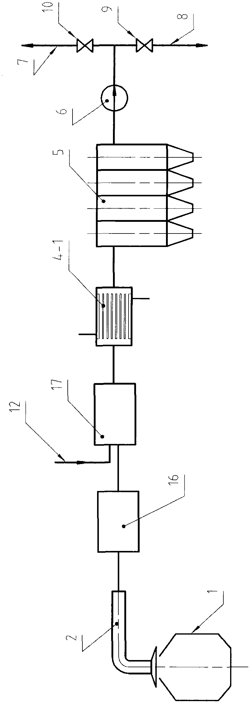
[0076] Example 2, such as figure 2 shown.

[0077] This embodiment is a simplification of Embodiment 1.

[0078] Compared with embodiment 1, it cancels the input channel 14 of combination device 3, switch valve 11, inert gas, blower fan 6 backflow switch valve 13 and water mist generator 15; and a separate combustion chamber 17 to replace the combination device 3; meanwhile, the heat exchange device 4 is replaced with a fire tube heat exchange device 4-1. The separate coarse dust collector 16 and the separate combustion chamber 17 are preferably also provided with a heat storage function, so as to obtain better use effects.

[0079] The working process of this embodiment is: the converter flue gas discharged from the flue heat exchange device 2 first enters the separate coarse dust collector 16 for preliminary dust removal, and keeps the coarse dust collector 16 at a relatively high temperature, and can carry out dedusting in it. The continued reaction of the gas and residu...


PUM


Abstract

The invention relates to a fuel gas injection type recovery method of sensible heat of convertor coal gas and convertor flue gas, and belongs to the technical field of recycling sensible heat of convertor coal gas and convertor flue gas. The main technical problems to be solved are as follows: on one hand, the water waste problem is to be solved, on the other hand, efficient utilization of physical sensible heat in the convertor flue gas is to be realized, and the effects of eliminating the potential safety hazard existing in the traditional system, greatly improving the yield of convertor coal gas and the like are also to be achieved. The method comprises allocation of a flue heat exchange device, a rough dust removing device and a refined dust removing device, an induced draft fan, a pipe network a control system, and is characterized in that a combustion chamber is arranged in a recovery system, fuel gas is injected into the combustion chamber, a heat exchanger is also arranged in the recovery system and the heat exchanger is installed behind the combustion chamber. The method is suitable for the technical field of recycling physical sensible heat in the convertor coal gas and convertor flue gas, and has the effects of saving energy, saving water, being safe, improving yield of convertor coal gas and the like.

Description

technical field [0001] The invention relates to a method for recovering the sensible heat of injected gas type converter gas and converter flue gas, and belongs to the technical field of recovering and utilizing the sensible heat of converter gas and converter flue gas. Background technique [0002] The converter gas recovery system is one of the process links widely used in the current metallurgical industry. Its main process equipment includes flue heat exchange device, cooling device, dust removal device, induced draft fan, switching station, pipe network and control system. The cooling device used in the existing system is a vaporization cooling tower, and the dust removal device used is an electrostatic precipitator and the like. [0003] The main problems with the existing system are: [0004] 1. The physical sensible heat in the converter flue gas is completely wasted in the process of vaporization and cooling. Since the flue gas volume of the converter is large, th...

Claims


Application Information

Patent Timeline
Patent Type & Authority Applications(China)
IPC IPC(8): C21C5/40F27D17/00
CPCY02P10/25
Inventor 黄东生钱纲李希昌盛振江刘鹏云贠汝平
Owner SHANDONG PROVINCE METALLURGICAL ENG CO LTD
Why Eureka
Try Eureka