Liquid feedstock plasma spraying device

A spraying device and plasma technology, applied in metal material coating process, coating, molten spraying, etc., can solve problems such as difficult to achieve stable powder delivery, affect the stability of spraying process, and difficult to prepare coatings, etc., to achieve the suppression of nano The particle growth phenomenon, the stability of the coating preparation process, and the effect of improving the coating preparation efficiency

Inactive Publication Date: 2013-04-10
CHINESE ACAD OF AGRI MECHANIZATION SCI +1
View PDF5 Cites 12 Cited by
  • Summary
  • Abstract
  • Description
  • Claims
  • Application Information

AI Technical Summary

Problems solved by technology

The preparation of spray powder by the above process has the disadvantages of complex process, high energy consumption, and low efficiency. More importantly, the powder is melted in the plasma jet and impacts on the substrate to form flat particles with a diameter of about 30 μm to 200 μm. Flattened particles tend to form transverse microscopic cracks and large-sized pores parallel to the coating surface, affecting coating performance
Small flat particles can be formed on the substrate by spraying fine raw material powders (such as submicron or nanometer powders) to eliminate the above-mentioned defects. However, when the size of the sprayed powder is less than 10 μm, the powder will form an uncontrollable agglomeration phenomenon due to electrostatic action, and its flow The stability is greatly reduced, and it is difficult to achieve stable powder delivery, which affects the stability of the spraying process
In addition, in the prior art, it is difficult to prepare coatings with a thickness between 20 μm and 100 μm in the plasma spraying process using powder as the spraying raw material, such as functional coatings applied on photocatalysis and solid oxide fuel cells (SOFC)

Method used


Image

  • Liquid feedstock plasma spraying device
  • Liquid feedstock plasma spraying device
  • Liquid feedstock plasma spraying device

Examples


Embodiment 1

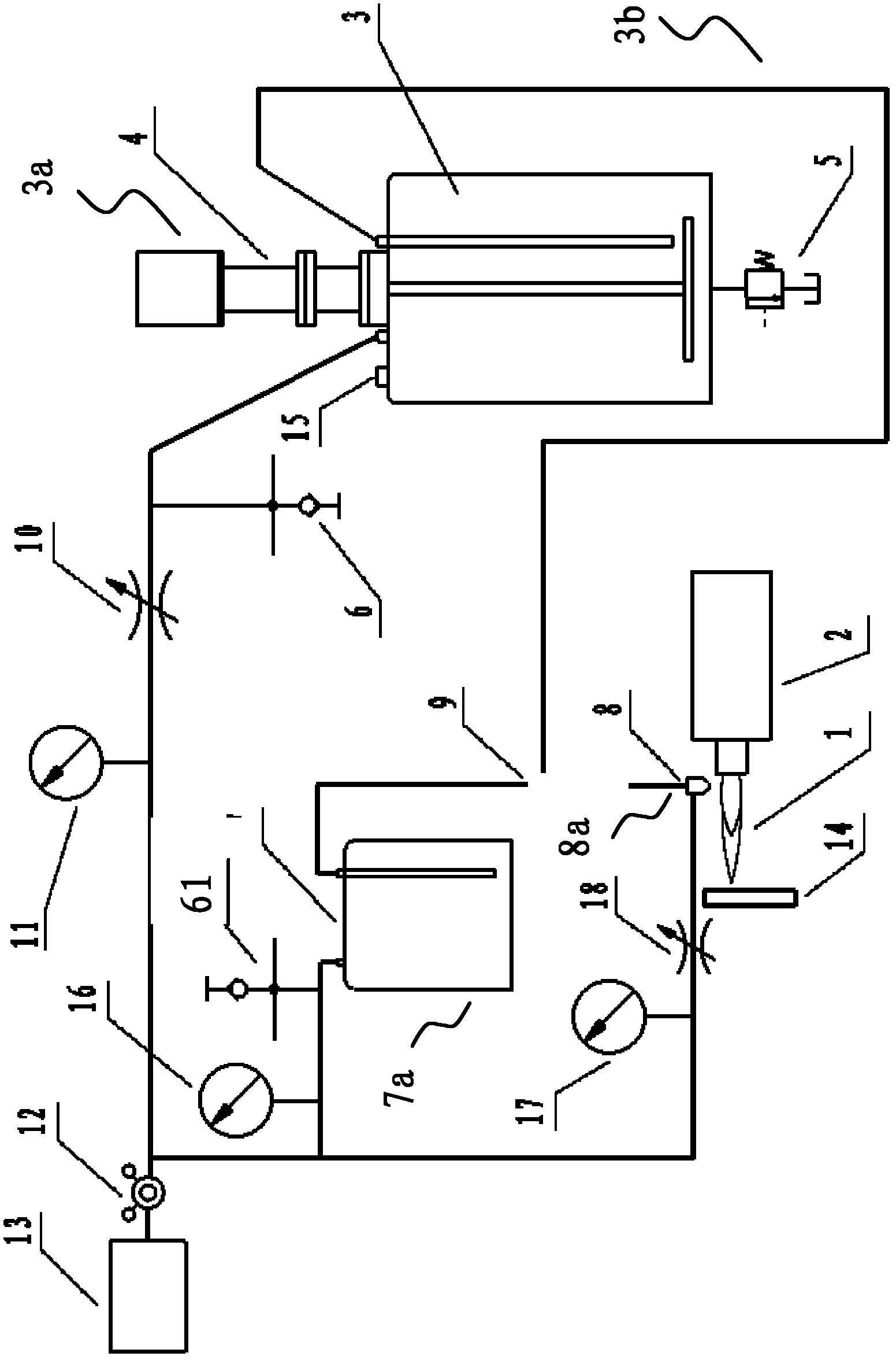
[0058] The liquid material plasma spraying device for preparing nanostructured thin ceramic coatings of the present invention includes a plasma system 2 and a liquid material delivery device 3a composed of a liquid material delivery system 3b, a liquid material injection system 8a and a cleaning system 7a. The liquid material delivery system 3b includes a liquid material storage pressure vessel 3 filled with compressed gas and corresponding gas and liquid material delivery pipelines, and the cleaning system 7a includes a cleaning medium storage pressure vessel 7 filled with compressed gas and corresponding gas and cleaning equipment. The medium conveying pipeline and the liquid material injection system 8a include a two-flow gas atomization nozzle 8 and corresponding tooling for clamping the two-flow gas atomization nozzle on the plasma system 2 and three-dimensionally adjustable. The liquid material is sent to the two-flow gas atomization nozzle 8 controlled independently by t...

Embodiment 2

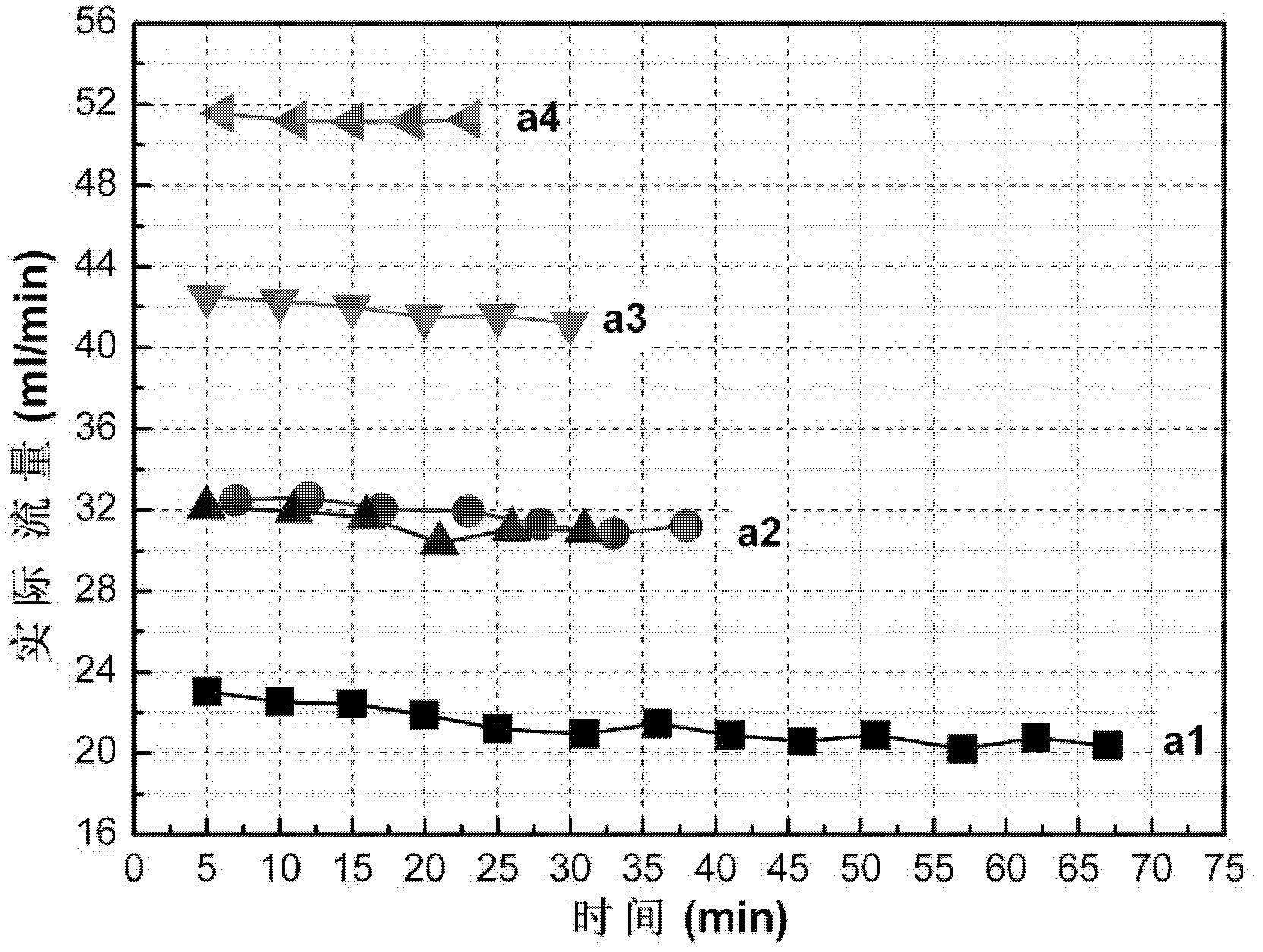
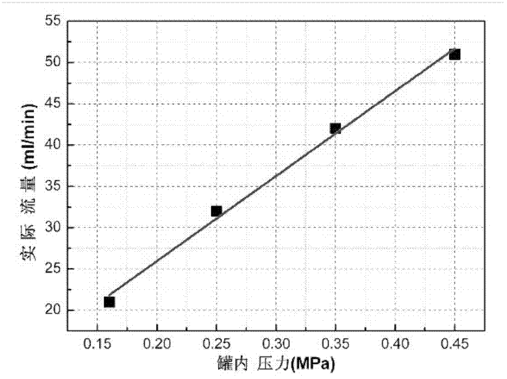
[0060] According to the technical scheme of the present invention, see Figure 2a and Figure 2b , Figure 2a , Figure 2b It is the curve of the solution precursor of yttria stabilized zirconia (YSZ) solution composed of zirconium salt and yttrium salt solution, which is quantitatively delivered by the liquid material delivery device according to an embodiment of the present invention. The solution precursor was tested under different tank pressures in the liquid material storage pressure vessel flow, Figure 2a Test at least 5 times under each pressure, each test is 5 minutes, and each test point in the figure is the average value of 5 minutes. The graphs a1, a2, a3, and a4 shown in the figure correspond to the flow rate of the solution precursor when the test pressure is 0.16MPa, 0.25MPa, 0.35MPa, and 0.45MPa respectively. At each test pressure, the flow rate of the solution precursor remains basically Constant, the flow fluctuation is less than ±5%. Figure 2b is the ...

Embodiment 3

[0062] The YSZ solution precursor is atomized through the two-flow gas atomization nozzle 8 at a flow rate of 25ml / min and then sent to the plasma jet 1. The atomization gas pressure is 0.1MPa. The YSZ coating is formed on the substrate 14 after processes such as solvent volatilization, solute precipitation, pyrolysis and melting. The surface morphology of the coating was observed with a scanning electron microscope, such as image 3 As shown, the results show that the coating has a nanostructure, the grain size is less than 100nm, and the flattened particle diameter is less than 5μm, which is far smaller than the flattened particle diameter of 30-200μm in the traditional plasma spray coating.


PUM

PropertyMeasurementUnit
thicknessaaaaaaaaaa
thicknessaaaaaaaaaa
particle sizeaaaaaaaaaa

Abstract

The invention provides a liquid feedstock plasma spraying device, which is used for the preparation of a ceramic coating in a nano structure on a basal body. The liquid feedstock plasma spraying device comprises a plasma system and a liquid feedstock conveying device, wherein the liquid feedstock conveying device comprises a liquid feedstock conveying system and a liquid feedstock injection system; the liquid feedstock conveying system comprises a gas source and a liquid feedstock conveying power device; the liquid feedstock conveying power device is connected with the gas source; the liquid feedstock injection system comprises a two-fluid gas atomization spray nozzle; the two-fluid gas atomization spray nozzle is connected with the liquid feedstock conveying power device; meanwhile, the two-fluid gas atomization spray nozzle is arranged in a manner of corresponding to a high temperature area of plasma jet of the plasma system and further connected with the gas source; moreover, the two-fluid gas atomization spray nozzle atomizes a liquid feedstock in the liquid feedstock conveying power device into liquid drops with certain speed and further sends the liquid drops into the high temperature area of the plasma jet; and after being heated by the plasma jet to speed up, the liquid drops are deposited on the basal body for the formation of the ceramic coating in the nano structure.

Description

technical field [0001] The invention relates to a coating preparation device, in particular to a liquid material plasma spraying device for preparing nanostructured thin ceramic coatings. Background technique [0002] Ceramic coatings prepared by traditional plasma spraying use ceramic powders with a certain particle size range, good fluidity, and moderate bulk density as spraying materials (such as Metco 204NS and Metco 106F, etc.). Co-precipitation-sintering method, co-precipitation-spray drying method, etc. For example, the Chinese invention patent application with application number "01128448.X" titled "Preparation method of nano-zirconia powder"; application number "200510045013.1" titled "Preparation method of zirconia nanomaterials for thermal barrier coating" ” Chinese invention patent application; the application number is “201010177581.8”, and the Chinese invention patent application named “Preparation method of alumina-titania composite ceramic powder”. The prep...

Claims


Application Information

Patent Timeline
Patent Type & Authority Applications(China)
IPC IPC(8): C23C4/12C23C4/10B82Y40/00C23C20/08
Inventor 王世兴汪瑞军徐林张辉刘毅
Owner CHINESE ACAD OF AGRI MECHANIZATION SCI
Why Eureka
Try Eureka