
Metal film preparation method

A metal thin film and thin film technology, applied in metal material coating process, ion implantation plating, coating and other directions, can solve the problems of poor step integrity, corrosion damage to the surface of the substrate, incomplete corrosion of the surface coating or over-corrosion, etc. The structure is complete and clear, preventing impurities from remaining, and avoiding the effect of impurity residues

Inactive Publication Date: 2013-06-05
GUANGDONG INST OF METROLOGY
View PDF1 Cites 12 Cited by
  • Summary
  • Abstract
  • Description
  • Claims
  • Application Information

AI Technical Summary

Problems solved by technology

The mechanical stripping method will cause damage to the substrate and the edge of the step is prone to deformation and distortion due to external force; the chemical etching method has very few chemical etching solutions to choose from, the corrosion edge of the coating is difficult to control, and the integrity of the step is poor; The corrosion method is difficult to accurately control the cut-off time of the electrolysis process, which makes the surface coating very prone to incomplete corrosion or over-corrosion, and the substrate surface is very easy to cause corrosion damage and film material residues

Method used

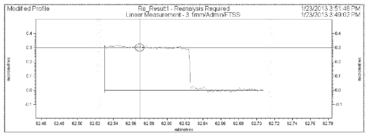
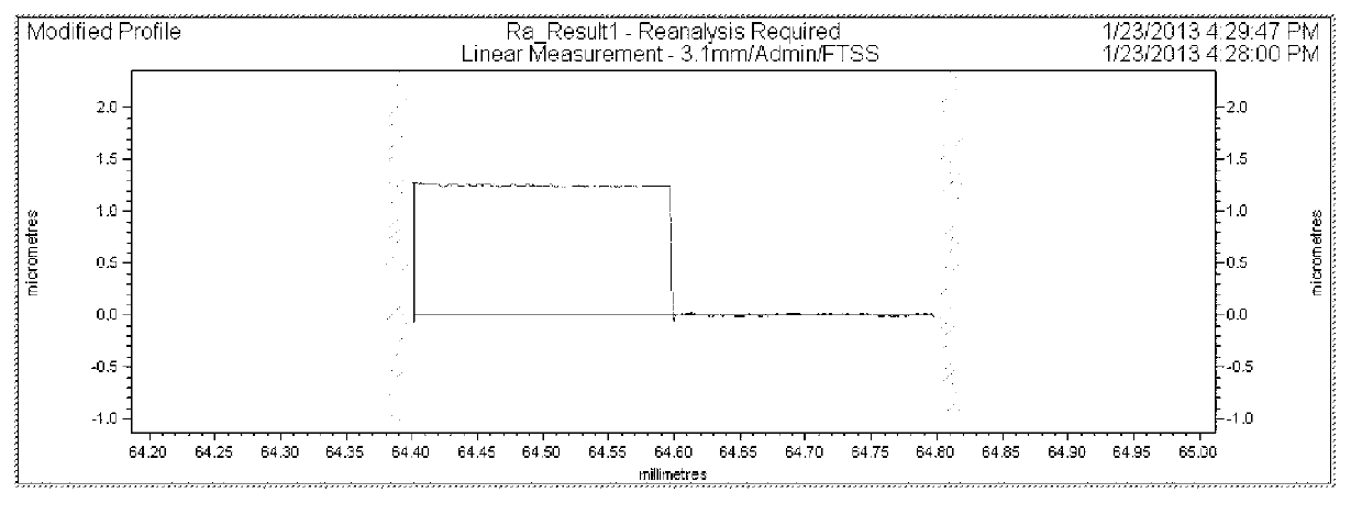
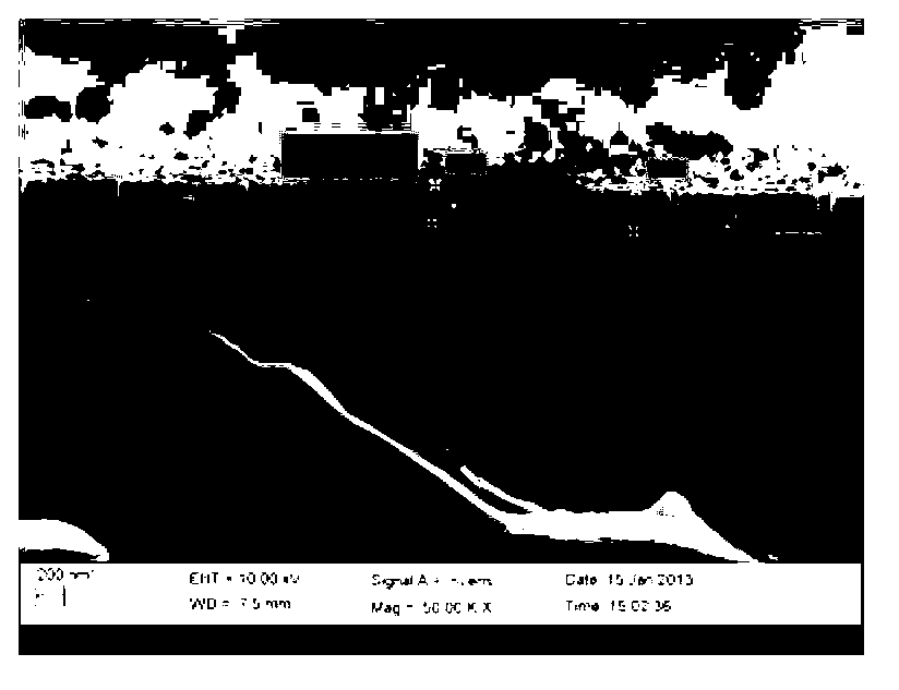

Image

  • Metal film preparation method
  • Metal film preparation method
  • Metal film preparation method

Examples


Embodiment 1~2

[0029] (1) Processing and surface treatment of nickel base material

[0030] Wire-cut pure nickel block (nickel purity over 99.9%) into a 5mm×5mm×5mm cube matrix. Mount samples on a mounting machine with epoxy resin. Use 400#, 600#, 800#, 1000# and 1200# metallographic sandpaper for mechanical grinding, and then polish with flannelette. After cleaning the surface with absolute ethanol, use a roughness tester to check that the surface roughness of the nickel substrate is 0.017 μm. Remove the epoxy resin coating by hammering or squeezing, place the taken out nickel substrate in absolute ethanol for ultrasonic cleaning for 20 minutes, and then dry it for later use.

[0031] (2) Partial glue protection on the surface of nickel substrate

[0032] Apply an appropriate amount of conductive silver glue evenly on one side of the printing plate with a thickness of 1mm, and use the printing plate to print a linear silver glue on the center of the surface of the nickel substrate. After...

Embodiment 3~10

[0039] Cut the blocks in Table 1 into substrates of corresponding specifications. Mount samples on a mounting machine using bakelite powder. Use 400#, 600#, 800#, 1000# and 1200# metallographic sandpaper to manually grind, and then polish with flannelette, so that the surface roughness of the metal substrate is less than 0.02 μm. Remove the bakelite coating by hammering or squeezing, place the metal substrate in absolute ethanol for ultrasonic cleaning according to the time in Table 1, and then dry it for later use.

[0040] Apply the adhesive shown in Table 1 evenly on the surface of the substrate by brushing.

[0041] After the adhesive dries to form an adhesive layer, a metal film is plated on the surface of the metal substrate and the adhesive layer. Place the metal substrate in the magnetron sputtering coating device and use the metal target vacuum coating as shown in Table 1. During the coating process, the temperature of the substrate is kept at room temperature, and ...


PUM

PropertyMeasurementUnit
Surface roughnessaaaaaaaaaa
Thicknessaaaaaaaaaa
Surface roughnessaaaaaaaaaa

Abstract

The invention discloses a metal film preparation method. The method comprises the following steps: 1, coating an adhesive in a selected area on the surface of a metal substrate; 2, allowing the adhesive to stand for drying to form an adhesive layer, and coating a metal film on the surface of the metal substrate and the adhesive layer; and 3, infiltrating the metal substrate in an organic solvent after the coating completion to soften the adhesive layer, and carrying out ultrasonic treatment of the metal substrate in the organic solvent to remove the adhesive layer to obtain a metal film having a stepped structure. The adhesive is coated to protect the partial surface of the substrate, and steps are formed on the surface of the film through the adhesive removal mode, so the completeness and edge clearness of the stepped structure of the metal film are guaranteed. The metal film prepared in the invention is suitable for contourgraphs and scanning probe microscopes to measure the heights of the steps of the metal film and standardize the thickness of the film, and is also used for the metering calibration of non-contact direct thickness testers (such as X-ray diffractometers and X-ray fluorescence thickness testers).

Description

technical field [0001] The invention relates to the field of metal thin films. Background technique [0002] The measurement of micro-nano-scale thin film thickness is an important content in the analysis of thin film properties. Accurate measurement of thickness is the need of thin film performance control, and also the need of later device processing applications (such as: photolithography, etc.). The growth of thin film can be controlled and optimized through the measurement of film thickness, and it can provide real-time monitoring device for more advanced thin film growth equipment (such as: molecular beam epitaxy, etc.). The film thickness of the micro-nano film directly determines the performance of the film. The film thickness index is extremely important in the fields of microelectronics and ultra-precision processing, and the accuracy of film thickness measurement is also an urgent problem to be solved. [0003] The measurement methods of metal film thickness mai...

Claims


Application Information

Patent Timeline
IPC IPC(8): C23C14/35C23C14/14C23C14/58
Inventor 张欣宇
Owner GUANGDONG INST OF METROLOGY
Learn More