Self-adaptive optical fiber coupler or collimator control system capable of bilaterally receiving and transmitting laser beams

A fiber coupling and control system technology, applied in the direction of lasers, phonon exciters, laser components, etc., can solve the problems of inconvenient use of liquid crystal phase controllers, lack of synchronous coupling of laser beams, and low control accuracy, and achieve favorable Array integration, high control precision, and the effect of improving the resonance frequency

Active Publication Date: 2013-09-18
成都芯智锐光科技有限公司
View PDF3 Cites 29 Cited by
  • Summary
  • Abstract
  • Description
  • Claims
  • Application Information

AI Technical Summary

Problems solved by technology

[0003] Chinese patent application [201110460843.6] "Efficient Spatial Light-Fiber Dynamic Coupling Method" proposes to use the PID control circuit to dynamically control the driving voltage of the liquid crystal phase controller according to the strength of the detected light signal, and change the phase of the converging beam to achieve efficient dynamic coupling. The control accuracy of the system is not high, and there are many inconveniences in the use of the liquid crystal phase controller
In 2012, H.Takenaka et al. achieved high-coupling-efficiency inter-satellite optical communication by controlling the high-speed tilting mirror to all

Method used


Image

  • Self-adaptive optical fiber coupler or collimator control system capable of bilaterally receiving and transmitting laser beams
  • Self-adaptive optical fiber coupler or collimator control system capable of bilaterally receiving and transmitting laser beams

Examples


Embodiment

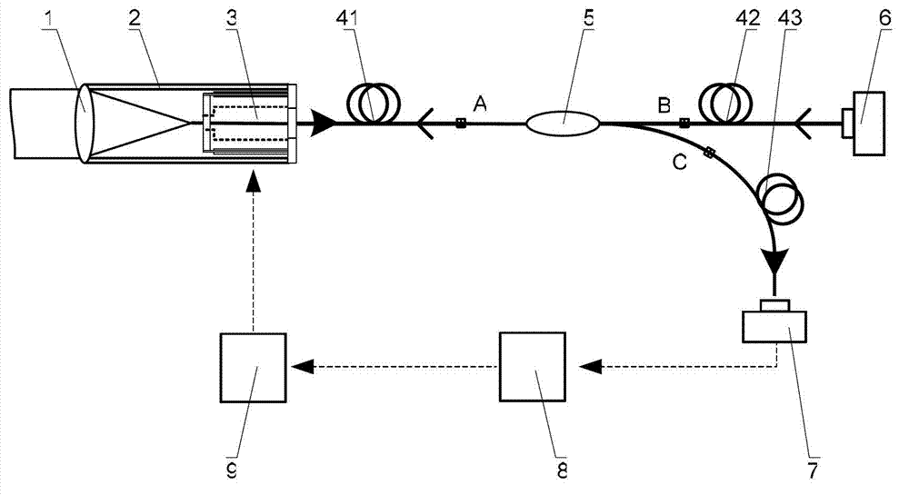
[0023] according to figure 1 , figure 2 Based on the structure, an adaptive fiber coupling or collimator control system for bidirectional transmission and reception of laser beams is designed. Based on the mode-field matching theory, the fiber coupling efficiency reaches a maximum of 81.45% when the coupling parameter β=1.13 (P.Winzer, and W.Leeb, "Fiber coupling efficiency for random light and its applications to ladar," Optics Letters23,986- 988 (1998)). Wherein, the coupling parameter is directly proportional to the aperture of the coupling or collimating lens 1 and the fiber mode field radius, and is inversely proportional to the focal length of the coupling or collimating lens and the laser wavelength. Accordingly, in the embodiment of the present invention, the first optical fiber 41, the second optical fiber 42 and the third optical fiber 43 adopt single-mode polarization-maintaining optical fibers, the fiber mode field radius is 5 μm, and the wavelength of the trans...


PUM


Abstract

The invention discloses a self-adaptive optical fiber coupler or collimator control system capable of bilaterally receiving and transmitting laser beams. The self-adaptive optical fiber coupler or collimator control system comprises a coupling or collimating lens, a connecting sleeve, an optical fiber end face positioner, a first optical fiber, a three-port optical fiber circulator, a second optical fiber, a third optical fiber, a laser, a photoelectric detector, a control platform and a high-voltage amplifier, wherein the optical fiber end face positioner comprises a flexible crossed beam, a bimorph driver, a damping material, a boss and a fixed seat. Due to the adoption of the self-adaptive optical fiber coupler or collimator control system, the light beam arriving angle errors caused by factors such as atmosphere turbulence, mechanical vibration, thermal distortion and the like can be corrected adaptively; and meanwhile, according to the reversibility principle of a light path, the transmitting angle correction of emitted collimating light beams is also realized. The self-adaptive optical fiber coupler or collimator control system has an important application prospect in the field of optical fiber-based laser space application, such as free space laser communication, laser precise positioning and laser radar.

Description

technical field [0001] The invention relates to an adaptive optical fiber coupling or collimator control system for two-way transmission and reception of laser beams, which can be used in optical fiber-based space laser application fields such as free space laser communication, laser atmospheric transmission, laser precision positioning, and laser radar. Background technique [0002] In the fiber-based space laser system, how to improve the space light coupling efficiency and reduce the signal-to-noise ratio is one of the key technical problems to be solved. In fact, due to atmospheric turbulence effects, mechanical platform vibration, and thermal distortion, the laser beam reaching the receiving end will produce an angle error, which greatly affects the fiber coupling efficiency. At the same time, factors such as atmospheric turbulence effects, mechanical platform vibration, and thermal distortion will also cause angle errors in the emitted laser beam, which affects the acc...

Claims


Application Information

Patent Timeline
IPC IPC(8): H01S3/10H01S3/067H01S5/06
Inventor 耿超罗文李新阳谭毅武云云刘红梅牟进博
Owner 成都芯智锐光科技有限公司
Why Eureka
Try Eureka