SOI power LDMOS device provided with junction type field plate
A junction field plate and device technology, which is applied in the direction of semiconductor devices, electrical components, diodes, etc., can solve the problems of large leakage current of resistance field plate and increase of device breakdown voltage, so as to reduce leakage current, reduce on-resistance, Effect of improving static electrical performance
- Summary
- Abstract
- Description
- Claims
- Application Information
AI Technical Summary
Problems solved by technology
Method used
Image
Examples
Embodiment 1
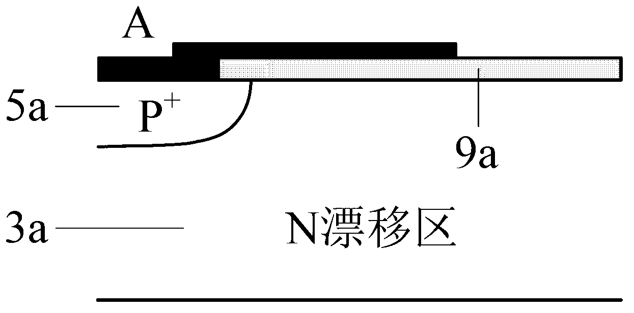
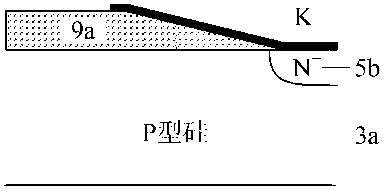
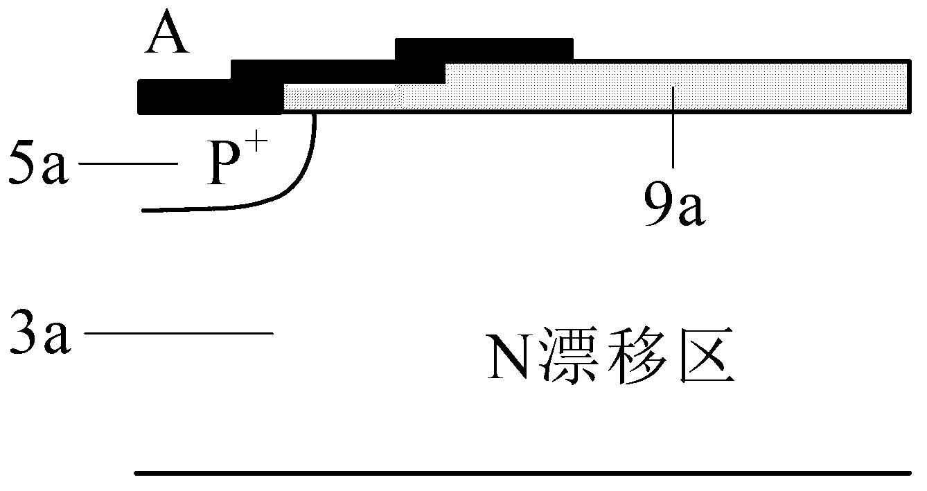
[0036] Fig. 6(a) shows a cross-sectional view of a half-cell structure of a JFP SOI LDMOS device using a trench gate structure. The devices in this example include:
[0037] It includes a substrate layer 1, a dielectric buried layer 2, and an active layer 3 vertically from bottom to top; the active layer 3 is a doped semiconductor of the first conductivity type, and has: a drain region 7c of a doped semiconductor of the first conductivity type , a source region 7b of a semiconductor doped with a first conductivity type, a body region 6 of a semiconductor doped with a second conductivity type, and a body contact region 7a of a semiconductor doped with a second conductivity type. The second conductivity type doped semiconductor body region 6 is located on one side of the surface of the active layer 3, the first conductivity type doped semiconductor source region 7b is adjacent to the second conductivity type doped semiconductor body contact region 7a and Located on the surface ...
Embodiment 2
[0042] Figure 7 A schematic diagram of half a cell structure of the JFP SOI LDMOS device of this embodiment is shown. Compared with Embodiment 1, the device of this embodiment inserts the first conductivity type doped semiconductor buffer zone 12 between the high resistance region 11 and the N-type ohmic contact region 10b in the junction field plate, and other structures are the same as Embodiment 1. The doping concentration of the first conductivity type doped semiconductor buffer area 12 is lower than the concentration of the ohmic contact of the junction field plate, so as to reduce the electric field peak at the PN junction of the field plate, thereby preventing the device from being placed at the PN junction of the field plate Early breakdown. Therefore, compared with the device of Example 1, the withstand voltage of the device in this example is relatively high.
Embodiment 3
[0044] Compared with Example 1, the device of this example injects a thinner (for example, about 0.5um) buffer layer 13 at the interface between the active layer and the buried dielectric layer, such as Figure 8 shown. For N-channel JFP SOI LDMOS devices, the buffer layer is N-type doped; at this time, the buffer layer 13 not only serves as a transmission channel for high current density, but also increases the vertical electric field at the interface between the active layer and the dielectric buried layer, thereby The electric field distribution in the dielectric buried layer is improved, which is beneficial to the improvement of the vertical withstand voltage of the device. The device in this example is only applicable to N-channel JFP SOI LDMOS devices.
PUM
 Abstract
Description
Claims
Application Information
 - R&D
- Intellectual Property
- Life Sciences
- Materials
- Tech Scout
- Unparalleled Data Quality
- Higher Quality Content
- 60% Fewer Hallucinations
Browse by: Latest US Patents, China's latest patents, Technical Efficacy Thesaurus, Application Domain, Technology Topic, Popular Technical Reports.
© 2025 PatSnap. All rights reserved.Legal|Privacy policy|Modern Slavery Act Transparency Statement|Sitemap|About US| Contact US: help@patsnap.com


