Unit of recovering flue gas waste heat and dust in nonferrous metal smelting
A waste heat recovery device, a technology for waste heat from flue gas, applied in waste heat treatment, lighting and heating equipment, and process efficiency improvement, etc. The effect of small size, large elastic modulus and high heat transfer efficiency
- Summary
- Abstract
- Description
- Claims
- Application Information
AI Technical Summary
Problems solved by technology
Method used
Image

Examples
Embodiment 1
[0063] A method for recycling waste heat and dust of non-ferrous metal copper smelting flue gas of the present invention
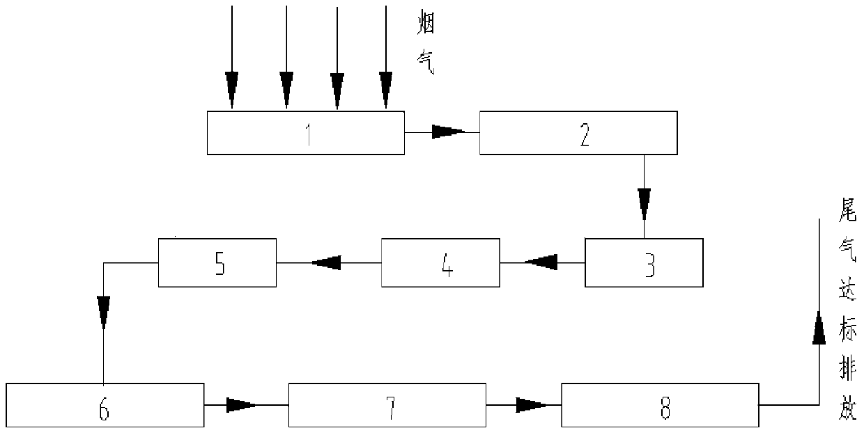
[0064] It includes a waste heat recovery device and a dust recovery device, which are characterized in that the waste heat recovery device and the dust recovery device are composed of a countercurrent heat exchange waste heat boiler A (1), a silicon nitride porous ceramic filter (2), and a countercurrent heat exchange waste heat boiler B ( 3), countercurrent heat exchange waste heat boiler working fluid preheater (4), sheet type channel gas countercurrent heat exchanger (5), bag filter dust collector (6), induced draft fan (7) are connected through pipelines or pipe fittings After being desulfurized in the flue gas desulfurization workshop (8) after recovery of waste heat and dust, the tail gas is discharged up to standard;
[0065] Described recycling method comprises the steps:
[0066] ①. Primary recovery of waste heat
[0067] The 1400°C flue gas fro...
Embodiment 2
[0082] A method for recycling waste heat and dust of non-ferrous metal copper smelting flue gas of the present invention
[0083] According to the method and step of embodiment 1, difference is:
[0084] ①. Flue gas temperature 1350℃
[0085] ②. The waste heat recovery device used in steps ①, ③, and ④ is the countercurrent heat exchange waste heat boiler A (1), the countercurrent heat exchange waste heat boiler B (3) and the countercurrent heat exchange waste heat boiler working fluid preheater (4). The heat exchange between the working fluids of the boiler adopts the three-tube countercurrent heat exchange method. The heat exchange device is composed of three straight tubes with different diameters. The gap tubes have opposite flow directions to realize countercurrent heat exchange.
[0086] The recovery rate of heat carried in the flue gas is ≥97%, and the recovery rate of smoke and dust is ≥98%.
Embodiment 3
[0088] A method for recycling waste heat and dust of non-ferrous metal copper smelting flue gas of the present invention
[0089] According to the method and steps of Example 1, the difference is: the heat exchange between the flue gas of the countercurrent heat exchange waste heat boiler A (1) and the boiler waste heat recovery working fluid adopts a double-pipe countercurrent heat exchange method;
[0090] ①. Flue gas temperature 1400℃
[0091] ②. The heat exchange between the flue gas of the countercurrent heat exchange waste heat boiler B (3) and the working medium preheater (4) of the countercurrent heat exchange waste heat boiler and the working medium of the boiler adopts the three-tube countercurrent heat exchange method.
[0092] The recovery rate of heat carried in the flue gas is ≥96%, and the recovery rate of smoke and dust is ≥98%.
PUM
 Abstract
Description
Claims
Application Information
 - R&D
- Intellectual Property
- Life Sciences
- Materials
- Tech Scout
- Unparalleled Data Quality
- Higher Quality Content
- 60% Fewer Hallucinations
Browse by: Latest US Patents, China's latest patents, Technical Efficacy Thesaurus, Application Domain, Technology Topic, Popular Technical Reports.
© 2025 PatSnap. All rights reserved.Legal|Privacy policy|Modern Slavery Act Transparency Statement|Sitemap|About US| Contact US: help@patsnap.com