Flue gas cleaning system and flue gas cleaning process for integrated multi-pollutant removal by dry method

A flue gas purification system and pollutant technology, applied in the field of flue gas purification system, can solve the problems of large overall resistance, large floor space, ammonia escape, etc., and achieve the effects of no waste water discharge, small floor space, and environmental friendliness

Active Publication Date: 2014-02-26
XIAN THERMAL POWER RES INST CO LTD +1
View PDF7 Cites 21 Cited by
  • Summary
  • Abstract
  • Description
  • Claims
  • Application Information

AI Technical Summary

Problems solved by technology

[0004] At the same time, in the process of coal combustion in my country, the loss on ignition of fly ash is relatively high, and the calcium oxide, magnesium oxide, and sulfur trioxide in the chemical components are also relatively high. In addition, the general load fluctuation of boiler operation is relatively large, resulting in the existing SCR system. Catalyst blockage, fouling, poisoning, ammonia escape, nitrogen oxide NO x Problems such as unstable removal rate and excessive energy consumption
Limestone-gypsum method and seawater desulfurization method have the disadvantages of large area, complex system, high energy consumption and high operating cost. For water-scarce areas such as Northwest my country, coal-fired units are more suitable for flue gas dry desulfurization process
There are a series of problems in the single removal of various pollutants, such as high overall cost, large overall resistance, large floor area, complex system, difficult operation and maintenance, etc.

Method used


Image

  • Flue gas cleaning system and flue gas cleaning process for integrated multi-pollutant removal by dry method

Examples


Embodiment Construction

[0024] The present invention will be described in further detail below in conjunction with the accompanying drawings.

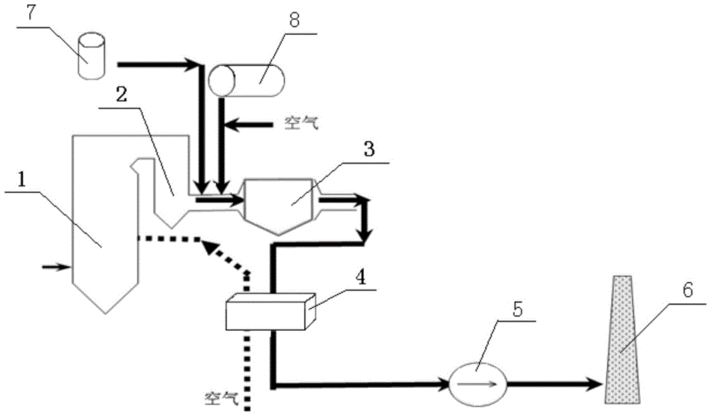
[0025] (1) see figure 1 , the system of the present invention includes an economizer 2 arranged at the tail of the boiler 1, and the outlet flue of the economizer 2 is sequentially connected with the integrated removal tower 3, the air preheater 4, the induced draft fan 5 and the smoke exhaust device, And the air preheater 4 is not only used to preheat the air entering the boiler 1 but also to preheat the purified flue gas, the induced draft fan 5 provides power for the whole system, and the smoke exhaust device is the chimney 6; the economizer 2 is integrated with On the flue between the removal towers 3, the first injection system for injecting the desulfurizer into the flue and the NO xThe second injection system in which the reducing agent is injected into the flue; in order to ensure a stable and efficient desulfurization effect, the desulfurizer uses C...


PUM


Abstract

Disclosed are a flue gas cleaning system and a flue gas cleaning process for integrated multi-pollutant removal by a dry method. The flue gas cleaning system comprises an economizer arranged at the tail of a boiler, and an outlet of the economizer is sequentially communicated with an integrated removal tower, an air preheater and a flue gas extractor; a first injection system and a second injection system are sequentially arranged on a flue between the economizer and the integrated removal tower; a catalytic ceramic filter bag is arranged in the integrated removal tower. After flue gas comes out from the flue at the tail of the economizer, SOx and HC1 in the flue gas react with desulfurizing agents, the desulfurizing agents and deacidified products which are not fully reacted and carried in the flue gas are mixed with ammonia gas prior to entering the integrated removal tower to have dust the unreacted desulfurizing agents, the deacidified products and NOx in a mixed system removed, and the flue gas is cleaned and discharged through the flue gas extractor. The flue gas cleaning system is small in occupied area, low in operation energy consumption, shortened in cleaning process and free of wastewater discharge.

Description

technical field [0001] The invention belongs to the field of integrated removal of atmospheric pollutants, and in particular relates to a flue gas purification system and process for integrated dry removal of multiple pollutants. Background technique [0002] Environmental and resource issues are major issues facing mankind today. The extensive use of fossil fuels such as coal, oil, and natural gas not only causes these energy sources to become increasingly scarce, but also produces a large amount of pollutants (such as dust, SO x , NO x , HCl, etc.), seriously affecting the environment and human health. [0003] With the stringent national environmental protection regulations, for dust, SO x , NO x The treatment of pollutants such as pollutants has been extensively carried out. Taking thermal power plants as an example, almost all thermal power plants in China have installed dust removal devices, and SCR and WFGD have also become the main technologies for denitration an...

Claims


Application Information

Patent Timeline
Patent Type & Authority Applications(China)
IPC IPC(8): F23J15/02B01D53/78B01D53/50B01D53/68B01D46/02B01D53/90B01D53/56
Inventor 牛国平谭增强
Owner XIAN THERMAL POWER RES INST CO LTD
Why Eureka
Try Eureka