Surface-mounted overvoltage and overcurrent protection device and manufacturing method thereof

An overvoltage and overcurrent protection, surface mount technology, used in overvoltage protection resistors, fuse manufacturing, emergency protection devices, etc., can solve the problems of small product capacitance, limited energy range, large printing area, etc. The effect of fast speed, improved reliability, and low cost

Active Publication Date: 2016-02-10
NANJING SART SCI & TECH DEV
View PDF6 Cites 0 Cited by
  • Summary
  • Abstract
  • Description
  • Claims
  • Application Information

AI Technical Summary

Problems solved by technology

Chinese Patent Application No. 200410104274.1 proposes a method of manufacturing a surface-mounted symmetrical structure overcurrent and overvoltage protector, and the overcurrent protection fuse element is surrounded by arc extinguishing material or arc shielding material, so that the product can protect the circuit from damage caused by relatively high voltage and high current; in addition, Chinese patent application number 200810215909.3 provides a method for manufacturing a glass ceramic ESD overvoltage protection device. This type of overvoltage protector has a low capacitance (<0.25pF), accurate Embedded (embedded voltage<50V), low leakage conductance, fast response, high stability and temperature resistance, etc., but because the electrostatic functional layer involved is a surface coating layer with a thickness of 5~30μm, the coating The printing area is generally relatively large and the thickness is thin, so the capacitance of the product cannot be made too small, and the range of energy it can withstand is also limited

Method used


Image

  • Surface-mounted overvoltage and overcurrent protection device and manufacturing method thereof
  • Surface-mounted overvoltage and overcurrent protection device and manufacturing method thereof
  • Surface-mounted overvoltage and overcurrent protection device and manufacturing method thereof

Examples


Embodiment 1

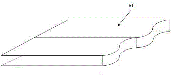
[0054] 1. Ingredients flow casting: select LTCC ceramic powder and pressure-sensitive ceramic material that meet the requirements to prepare slurry respectively. The sintering temperature of the two ceramic materials should be within the same temperature range, and their dielectric constant should be as small as possible. Generally, ceramic materials with a dielectric constant less than 10 are selected; LTCC ceramics can use common materials such as glass-ceramic systems or glass / ceramic composite systems, and mix them into qualified slurry through ball milling or sand milling, and then through casting process Obtain a certain width and thickness such as image 3 The shown LTCC ceramic diaphragm 61; the varistor functional phase 52 are mainly made of zinc oxide, tin oxide, strontium titanate and other materials with non-linear pressure-sensitive characteristics, mixed by ball milling, and the varistor ceramic powder, solvent, viscous Mixture and dispersant can be prepared into...

Embodiment 2

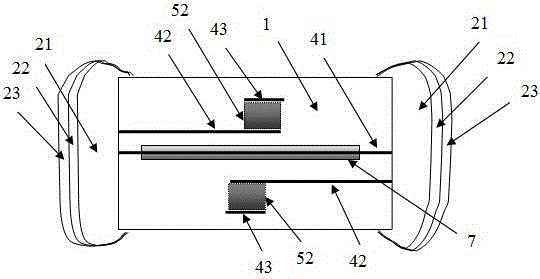
[0066] like Figure 11 As shown, according to the stacking sequence number described in step 8 in Example 1, the stacking method is changed to: a) stacking the lower protective layer 611 --> b) stacking the second electrode layer 43 --> c) stacking LTCC ceramics Diaphragm 5-->d) stacked first electrode layer 42-->e) stacked arc-extinguishing material coating 7-->f) stacked melt layer electrode pattern 41-->g) stacked arc-extinguishing material coating 7 -->f) Stacked melt layer electrode pattern 41 -->g) Stacked arc extinguishing material coating 7 -->h) Stacked first electrode layer 42 -->i) Stacked LTCC ceramic stacked diaphragm 5 --> j) stacking the second electrode layer 43 --> k) stacking the lower protective layer 612 to form a structure in which two layers of melt layer electrode patterns 41 are connected in parallel.

[0067] Others are made in the same manner as in Example 1.

Embodiment 3

[0069] like Figure 12 As shown, according to the stacking sequence number described in step 8 in Example 1, the stacking method is changed to: a) stacking the lower protective layer 611 --> d) stacking the first electrode layer 42 --> c) stacking LTCC ceramics Diaphragm 5-->b) stacked second electrode layer 43-->c) stacked LTCC ceramic stacked diaphragm 5-->d) stacked first electrode layer 42-->e) stacked arc-extinguishing material coating 7- ->f) Stacked melt layer electrode pattern 41-->g) Stacked arc-extinguishing material coating 7-->h) Stacked first electrode layer 42-->i) Stacked LTCC ceramic stacked diaphragm 5-->j ) stacking the second electrode layer 43 --> i) stacking the LTCC ceramic stack diaphragm --> h) stacking the first electrode layer 42 --> k) stacking the lower protective layer 612 to form an overvoltage and overcurrent protection device .

[0070] Others are made in the same manner as in Example 1.


PUM


Abstract

The invention provides a surface-mounted overvoltage and overcurrent protection device and a manufacturing method thereof, comprising a protection device body, end electrodes are provided at the left and right ends of the protection device body, and side electrodes are provided at the front and rear sides to protect the device body. The device body is provided with at least one melt layer electrode, at least two first electrode layers, and at least two second electrode layers, and the melt layer electrode is covered by an arc-extinguishing material coating, the first electrode layer and the second electrode layer There are through holes between the electrode layers and they are filled with piezoresistive functional phases. Forming through LTCC ceramic diaphragm --> melt layer electrode printing --> electrode layer electrode printing --> arc extinguishing material coating printing --> forming a through hole in the LTCC ceramic stack diaphragm --> filling pressure in the through hole Functional phase of the sensitive resistor --> stacked according to the design --> cut into a single product --> product sintering --> forming end electrodes and side electrodes and other steps. It has the advantages of low capacitance, low leakage current, fast response, high reliability and stability.

Description

technical field [0001] The invention relates to an overvoltage and overcurrent protection device, in particular to a protection device which can realize low-temperature co-firing and is suitable for surface mounting, and integrates overvoltage and overcurrent protection functions, and a manufacturing method of the device. Background technique [0002] With the rapid development of electronic technology and the upgrading of electronic products, people's requirements for product reliability and safety are increasing day by day. On various low-voltage electrical appliances, they are often impacted by surge currents caused by unexpected voltage transients, which will lead to deterioration of the performance of electronic products, prone to malfunction or even damage, and interfere with the normal operation of the system, eventually causing the entire machine The reliability performance of the equipment is reduced. Therefore, transient overcurrent and overvoltage protection are ...

Claims


Application Information

Patent Timeline
Patent Type & Authority Patents(China)
IPC IPC(8): H01H85/041H01H85/05H01H69/02H01C7/12H01C17/00
Inventor 南式荣刘明龙
Owner NANJING SART SCI & TECH DEV
Why Eureka
Try Eureka