A horizontally opposed high-voltage and low-voltage power equipment and its work method

A horizontally opposed, power equipment technology, used in mechanical equipment, machines/engines, hot gas variable capacity engine devices, etc., can solve the problems of high manufacturing cost and high cost, and achieve low manufacturing cost, low center of gravity, and good stability. Effect

Active Publication Date: 2015-10-07
郭远军
View PDF7 Cites 2 Cited by
  • Summary
  • Abstract
  • Description
  • Claims
  • Application Information

AI Technical Summary

Problems solved by technology

[0015] The invention overcomes the high cost of the expansion chamber, compression chamber, heater, cooling chamber, regenerator, etc. in the Stirling engine, and the heat loss is 2-3 times that of the internal combustion engine; it overcomes the need for an organic Rankine cycle system. Expander or steam turbine, a technical problem with high manufacturing costs

Method used


Image

  • A horizontally opposed high-voltage and low-voltage power equipment and its work method
  • A horizontally opposed high-voltage and low-voltage power equipment and its work method

Examples


Embodiment 1

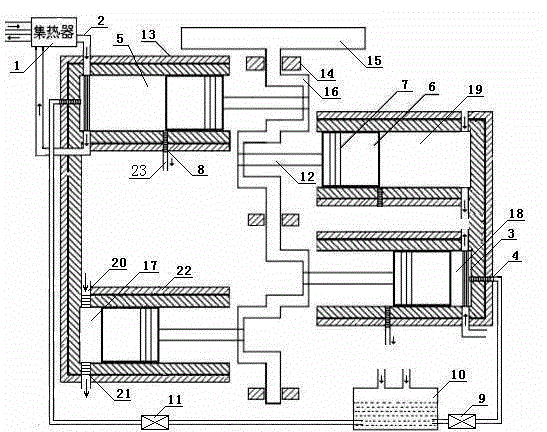
[0029]A horizontally opposed high and low pressure power equipment, including heat collector 1, heat preservation pipe 2, gasification reactor 3, atomizer 4, high pressure cylinder I5, piston 6, piston ring 7, automatic exhaust valve 8, pressure valve I9, liquid storage tank 10, pressure valve II11, connecting rod 12, insulation layer 13, casing 14, flywheel 15, crankshaft 16, low-pressure cylinder I17, high-pressure cylinder II18, low-pressure cylinder II19, intake check valve 20, exhaust Control valve 21, radiator 22 and buffer pipe 23; high-pressure cylinder I5 and low-pressure cylinder II19, low-pressure cylinder I17 and high-pressure cylinder II18 are arranged horizontally on the casing at an angle of 180° with the crankshaft as the center, high-pressure cylinder I5, low-pressure cylinder II19, low-pressure cylinder I17 and high-pressure cylinder II18 are provided with piston 6, piston 6 is provided with piston ring 7, piston 6 is connected with connecting rod 12, connecti...

Embodiment 2

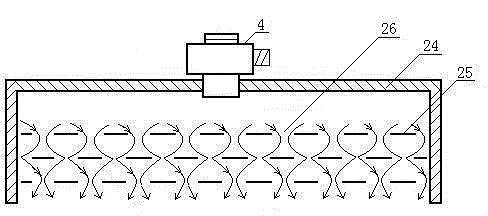
[0031] As in the horizontally opposed high and low pressure power equipment in the above-mentioned embodiment 1, the radiator 22 is made into a heat sink form; a circulating pipeline is arranged on the radiator 22 and a circulating cooling medium is injected in the pipeline; The exhaust control valve 21 on the I17 and low-pressure cylinder II19 can automatically adjust the exhaust according to the temperature of the hot gas source; the intake check valve 20 is arranged in the middle of the top of the low-pressure cylinder I17 and the low-pressure cylinder II19; The circulating cooling medium water is injected inside, and the circulating water is used for cooling; the gasification reactor 3 includes a pressure shell 24, a gasification heat conduction sheet 25, an air hole 26, and an atomizer 4, and the gasification heat conduction sheet 25 is arranged on the pressure shell 24 , The gasification heat conducting sheet 25 is provided with an array of air holes 26 , and the air inle...


PUM


Abstract

The invention relates to a horizontally opposed type high and low pressure power device and a working method thereof. The horizontally opposed type high and low pressure power device comprises a heat collector, an insulation pipe, a gasification reactor, an atomizer, a high pressure cylinder I, pistons, piston rings, automatic exhaust valves, a pressure valve I, a liquid storage tank, a pressure valve II, connection rods, insulation layers, a machine case, a flywheel, a crankshaft, a low pressure cylinder I, a high pressure cylinder II, a lower pressure cylinder II, air inlet check valves, exhaust control valves and a radiator, wherein the high pressure cylinder I, the lower pressure cylinder II, the low pressure cylinder I and the high pressure cylinder II are arranged on the machine case in a horizontally opposed mode at 180 degrees with the crankshaft as the center. The horizontally opposed type high and low pressure power device has the advantages that a work medium is recycled without pollution, heat energy conversion efficiency ranges from 65% to 98%, the output power is adjusted by adjusting the volume and number of the cylinders of the machine as required, injected liquid and output power can be adjusted in the largest power range, the machine is simple in structure, low in manufacturing cost, high in economic efficiency, energy-saving, environment-friendly, low in noise, gravity and vibration and good in stability.

Description

technical field [0001] The invention belongs to the field of negative pressure power equipment, and especially uses heat energy such as solar energy, geothermal heat, high-temperature gas generated by combustion of combustibles, exhaust gas of an internal combustion engine, high-temperature gas discharged from factories, etc. to make the medium gas in the machine and the heat radiation outside the machine form a temperature difference, so that A closed cylinder generates negative pressure to convert heat energy into kinetic energy. Background technique [0002] Traditional power equipment includes steam engine, internal combustion engine and external combustion engine. [0003] Steam engine: Inseparable from the boiler, the whole device is bulky and bulky; the pressure and temperature of the fresh steam cannot be too high, the exhaust pressure cannot be too low, and the thermal efficiency is difficult to improve; it is a reciprocating machine, and the inertia limits the incr...

Claims


Application Information

Patent Timeline
Patent Type & Authority Patents(China)
IPC IPC(8): F02G1/044F02G1/053
Inventor 郭远军
Owner 郭远军
Why Eureka
Try Eureka