Inorganic high temperature resistant low infrared emissivity composite coating and preparation method thereof

A low-infrared emission, inorganic high temperature resistant technology, applied in chemical instruments and methods, layered products, metal layered products, etc. Improved temperature and high temperature stability, prevention of residual carbon contamination, ensuring low emissivity

Active Publication Date: 2016-03-02
NAT UNIV OF DEFENSE TECH
View PDF3 Cites 0 Cited by
  • Summary
  • Abstract
  • Description
  • Claims
  • Application Information

AI Technical Summary

Problems solved by technology

The low-emissivity functional coating of the organic system is not used at a high temperature, and the organic systems that can withstand above 200°C include: modified epoxy systems, organic silicon systems, modified phenolic systems, etc., but organic coatings that can work above 400°C Few, so not suitable for harsh use on aircraft
Low-emissivity functional coatings of inorganic systems have a wider temperature range, but most systems do not work well in high-temperature environments
The main reasons for the above defects are that there are few low-emissivity materials with stable performance in high temperature environments, and the second is that the materials are more likely to diffuse at high temperatures, resulting in deterioration of the performance of the functional phase.
[0004] The current inorganic materials with high temperature resistance and low emissivity include lead oxide coating, bismuth oxide coating, high-quality tin-doped indium oxide (ITO) coating and aluminum-doped zinc oxide (AZO) coating, etc. Low emissivity, but there are still defects such as material diffusion between coatings and unstable material properties in high temperature environments, resulting in increased emissivity of coatings in high temperature environments
In the prior art, researchers have prepared composite coatings such as Ni / Au / Pt, Ni / Au, and Pt on the surface of Ni alloys. The results show that the noble metal thin film has low emissivity and excellent high-temperature oxidation resistance. Diffusion of elements between substrates is serious, and the metal surface is easily stained, so it is not suitable for use at the end of the engine and high-temperature exhaust system

Method used


Image

  • Inorganic high temperature resistant low infrared emissivity composite coating and preparation method thereof
  • Inorganic high temperature resistant low infrared emissivity composite coating and preparation method thereof
  • Inorganic high temperature resistant low infrared emissivity composite coating and preparation method thereof

Examples


Embodiment 1

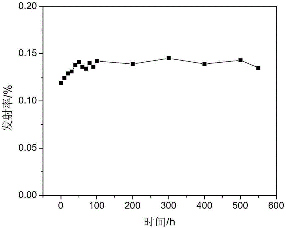
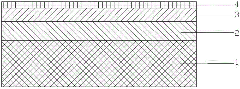
[0034] a kind of like figure 1 and figure 2 The inorganic high-temperature-resistant and low-infrared-emissivity composite coating shown is a multi-functional layer superposition structure, and the multi-functional layer superposition structure includes an oxidation barrier layer 2, a low-emission High-efficiency functional layer 3 and protective film 4, each layer is connected by mechanical bonding and chemical bonding, wherein the oxidation barrier layer is ZnO-Al 2 o 3 -SiO 2 Glass ceramic thin film, low emissivity functional layer is Pt thin film, protective film is TiO 2 film. The inorganic high-temperature-resistant low-infrared emissivity composite coating of this embodiment is deposited on the base material 1 of the GH3030 high-temperature nickel-based alloy plate. In this embodiment, the thickness of the oxidation barrier layer 2 is 3.0 μm, the thickness of the low-emissivity functional layer 3 is 1.5 μm, and the thickness of the protective film 4 is 1.0 μm.

...

Embodiment 2

[0043] a kind of like figure 1 The inorganic high-temperature-resistant and low-infrared-emissivity composite coating shown is a multi-functional layer superposition structure, and the multi-functional layer superposition structure includes an oxidation barrier layer 2, a low-emission High-efficiency functional layer 3 and protective film 4, each layer is connected by mechanical bonding and chemical bonding, wherein the oxidation barrier layer is ZnO-Al 2 o 3 -SiO 2 Glass ceramic thin film, low emissivity functional layer is Pt thin film, protective film is TiO 2 film. The inorganic high-temperature-resistant low-infrared emissivity composite coating of this embodiment is deposited on the base material 1 of the Inconel600 high-temperature nickel-based alloy plate. In this embodiment, the thickness of the oxidation barrier layer 2 is 4.0 μm, the thickness of the low-emissivity functional layer 3 is 3.0 μm, and the thickness of the protective film 4 is 0.5 μm.

[0044] In t...

Embodiment 3

[0052] a kind of like figure 1The inorganic high-temperature-resistant and low-infrared-emissivity composite coating shown is a multi-functional layer superposition structure, and the multi-functional layer superposition structure includes an oxidation barrier layer 2, a low-emission High-efficiency functional layer 3 and protective film 4, each layer is connected by mechanical bonding and chemical bonding, wherein the oxidation barrier layer is ZnO-Al 2 o 3 -SiO 2 Glass ceramic thin film, low emissivity functional layer is Pt thin film, protective film is TiO 2 film. The inorganic high-temperature-resistant low-infrared emissivity composite coating of this embodiment is deposited on the base material 1 of the GH4169 high-temperature nickel-based alloy plate. In this embodiment, the thickness of the oxidation barrier layer 2 is 5.0 μm, the thickness of the low-emissivity functional layer 3 is 1.0 μm, and the thickness of the protective film 4 is 0.8 μm.

[0053] In the in...


PUM

PropertyMeasurementUnit
thicknessaaaaaaaaaa
thicknessaaaaaaaaaa
thicknessaaaaaaaaaa

Abstract

The invention discloses an inorganic high-temperature-resistant low-infrared-emissivity composite coating which is of a multifunctional layer overlapped structure. The inorganic high-temperature-resistant low-infrared-emissivity composite coating comprises an oxidation blocking layer, a low-emissivity functional layer and a protective film in sequence from inside to outside, wherein all layers are combined mainly in a mechanical bonding mode and a solid-phase diffusion bonding mode, a ZnO-Al2O3-SiO2 glass ceramic film is used as the oxidation blocking layer, a Pt film is used as the low-emissivity functional layer, and a TiO2 film is used as the protective film. The preparation method comprises the following steps: polishing, cleaning and drying alloy base materials; depositing the glass ceramic film by virtue of radio frequency magnetron sputtering, and then depositing the Pt film by virtue of direct-current magnetron sputtering; and finally, depositing the TiO2 film by virtue of direct-current magnetron sputtering reaction. The composite coating product disclosed by the invention can be continuously used for more than 500 hours in the high-temperature environment of 800 DEG C, and the emissivity and high-temperature stability are obviously improved.

Description

technical field [0001] The invention belongs to the technical field of functional coating materials and preparation, and in particular relates to a high-temperature-resistant low-infrared emissivity composite coating that can be used on alloy surfaces and a preparation method thereof. Background technique [0002] The infrared detector collects the infrared signals of the target in the 3μm-5μm and 8μm-14μm bands, and then uses the difference in infrared radiation energy between the target and the background to identify the target through imaging. According to the calculation formula of infrared radiation energy difference: In the formula, ε 目 is the infrared emissivity of the target, ε 背 is the infrared emissivity of the background, T 目 is the surface temperature of the target, T 背 It can be seen that reducing the surface temperature of the target can make the radiation intensity of the target and the background similar, and preparing a low-emissivity functional coating...

Claims


Application Information

Patent Timeline
Patent Type & Authority Patents(China)
IPC IPC(8): B32B9/04B32B15/04C23C14/35
Inventor 李俊生程海峰周永江郑文伟童思超
Owner NAT UNIV OF DEFENSE TECH
Why Eureka
Try Eureka