Novel energy conversion system

An energy conversion system and energy conversion technology, applied in steam engine installations, machines/engines, mechanical equipment, etc., can solve problems such as inability to transplant low-grade marine thermal power generation technology, difficult pipeline fixed construction operations, and increased investment costs.

Inactive Publication Date: 2015-03-25
忻元敏
View PDF0 Cites 4 Cited by
  • Summary
  • Abstract
  • Description
  • Claims
  • Application Information

AI Technical Summary

Problems solved by technology

[0004] (1) The inevitable strong winds and waves in the ocean require that the safety factor of such power generation equipment and power plant buildings must be improved, so the initial investment cost increases;
[0005] (2) Seawater contains almost all elements in nature, so seawater constitutes an inevitable serious erosion of equipment, resulting in a greatly shortened expected service life of investment equipment, which is manifested in increased maintenance costs;
[0006] (3) In order to obtain the water source of the ocean surface or deep layer, it is not only extremely difficult to fix the pipeline at a depth of about 1,000 meters under the sea, but also has high risks and high costs, and the power consumption of the two high-power pumping systems takes up A large part of the system's power generation, so the power generation efficiency of the entire system is significantly reduced, which is reflected in the increase in unit electricity cost;
[0007] (4) Alternating seasons and lower sea surface temperature will make it difficult to maintain this power generation method. Although there are remedial ideas for combining solar energy and wind energy, they are not always effective. Therefore, the power generation efficiency of this type of power generation system in a year or in a day Large fluctua...

Method used


Image

  • Novel energy conversion system
  • Novel energy conversion system
  • Novel energy conversion system

Examples


example 1

[0045] Example 1. Common scheme

[0046] This scheme is suitable for general heat source occasions, including the use of natural environmental heat sources or artificial environmental heat sources, such as factory waste heat, and the water or gas of the heat source needs to be input into the gas-liquid phase combined heat exchange component through the action of a pump or an air pump, so it is called Ordinary program.

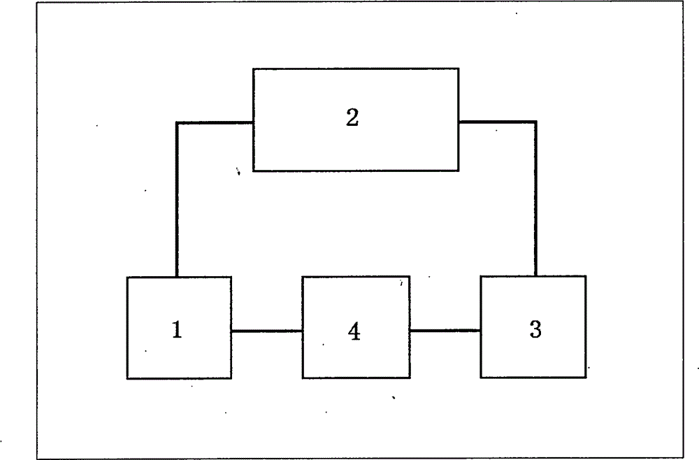
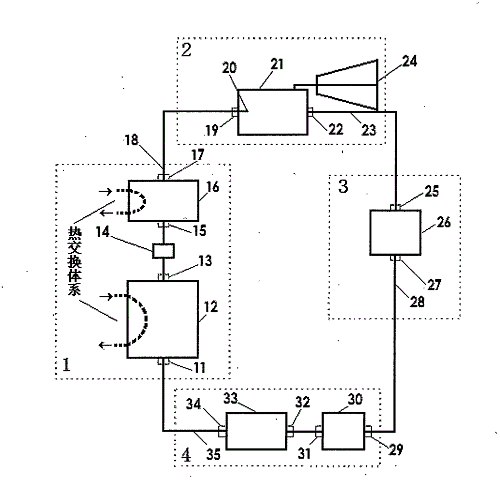
[0047]The heat accumulation mechanism 1, the energy conversion mechanism 2, the cooling and liquefaction mechanism 3 and the working medium circulation mechanism 4 are connected by pipelines in sequence. That is, the liquid inlet valve 11, the liquid phase heat exchanger 12, the check valve 13, the electronic expansion valve 14, the intake valve 15, the gas phase heat exchanger 16, the gas outlet valve 17 in the heat accumulation mechanism 1, and the energy conversion mechanism 2 Inlet valve 19, nozzle 20, pneumatic components 21, outlet valve 22, and inlet va...

example 2

[0051] Example 2. Energy-saving and high-efficiency solution

[0052] Compared with Example 1, this scheme is called energy-saving and high-efficiency type, because it does not need to pump water or air, which reduces the power consumption of water pumping or air pumping, so it is energy-saving and efficient. It is suitable for mountainous rivers with a water temperature above 25-10℃ all year round, with a certain water level gradient, or a certain flow rate, and is also suitable for outputting water flow or airflow in a factory waste heat type with a positioning difference and a certain pressure.

[0053] The system of this scheme is basically the same as Example 1, and the power generation mode is also the same, the difference is how to obtain the heat source water or gas process. In this scheme, the gas-liquid phase combined heat exchange components 12, 16 are directly placed in the flowing river water, so the water (gas) side of the heat exchange system of the gas-liquid p...

example 3

[0054] Example 3. Low-temperature photothermal water storage scheme

[0055] Compared with Example 1, this scheme is called low-temperature photothermal water storage type, because heat storage facilities and light field facilities are added to solve the heat source problem in areas with higher latitude and lower temperature. It is especially suitable for inland environments with long sunlight and unsatisfactory water sources, or marine or lake river environments with sufficient water sources but large temperature differences between day and night.

[0056] The system of this scheme is basically the same as Example 1, and the power generation mode is also the same, the difference lies in the intervention and preparation of the external heat source. In this solution, the light field focusing mirror array uses sunlight to focus and heat the aqueous solution in the storage tank during the daytime. The aqueous solution in the storage tank is the heat source of the system. General...


PUM


Abstract

The invention discloses a novel energy conversion system. The novel energy conversion system includes a heat aggregation mechanism, an energy conversion mechanism, a cooling and liquefying mechanism, and a working medium circulation mechanism which are connected in a pairwise manner. The whole system accords with the operating principle of the Rankine heat engine cycle system and the second law of thermodynamics. In the heat aggregation mechanism, a gas-liquid phase combined heat exchange component is used for technological aggregation and transfer of heat from a natural environmental heat source or an artificial environmental heat source to a working medium; in the cooling and liquefying mechanism, a forced type condenser technology is used to achieve effective heat dissipation and liquefaction of a working medium tail gas; in the working medium circulation mechanism, a working medium pump and a liquid storage tank are used to achieve the possibility of circulatory movements of the working medium in a closed system; in the energy conversion mechanism, an energy conversion assembly is used to convert the heat energy of working medium gas flows entering the mechanism into mechanical energy, or further convert the mechanical energy into electric energy. The energy conversion system provided by the invention is an improved and innovative energy conversion system, which can utilize energies, including but not limited to various low-grade heat energies, and convert the low-grade heat energies into mechanical power for work. The novel energy conversion system is a novel power generation system when connected with a power generator.

Description

Technical field: [0001] The invention relates to a novel energy conversion system. Background technique: [0002] With the shortage of energy resources in the world and the aggravation of environmental pollution, people pay attention to and realize how to develop and utilize the huge amount of low-grade heat energy that actually exists in natural space and waters. This low-grade thermal energy is essentially the heat given to the earth by solar radiation, so it is inexhaustible and inexhaustible, and it is the most green, clean, environmentally friendly and renewable cycle. At present, countries all over the world are investing and competing with each other, trying to gain a leading position in the field of developing and utilizing ocean low-grade thermal energy power generation technology, which greatly promotes the rapid development of ocean low-grade thermal energy power generation technology, making this power generation technology already commercially valuable . [00...

Claims


Application Information

Patent Timeline
IPC IPC(8): F01K25/00
Inventor 忻元敏
Owner 忻元敏
Why Eureka
Try Eureka