A continuous flow anaerobic biocathode microbial fuel cell

A fuel cell and anaerobic biological technology, applied in the field of environmental protection technology and new energy, can solve the problems of unfavorable volume, unsuitable hydraulic conditions for continuous inflow of water, unsuitable for continuous removal of oxidative pollutants in water, etc., so as to reduce pressure , to ensure the effect of long-term stable operation

Active Publication Date: 2017-05-03
温州嘉伟环保科技有限公司
View PDF2 Cites 0 Cited by
  • Summary
  • Abstract
  • Description
  • Claims
  • Application Information

AI Technical Summary

Problems solved by technology

[0005] However, existing microbial fuel cells still have many defects and are not suitable for continuous removal of oxidative pollutants in water.
First, due to the asymmetry of the number of electrons required to treat sludge and sewage, existing fuel cells need to treat sewage and sludge separately, and usually use potassium ferricyanide and glucose as cathode and anode fuels, which are costly and easy to process. cause secondary pollution
The second is that most of the existing fuel cells have a left and right chamber structure, which is not conducive to increasing the volume and increasing the daily processing capacity
Third, the hydraulic conditions of the traditional cube-shaped fuel cell are not suitable for continuous inflow of water, which is not conducive to the long-term stable power generation of the battery
Fourth, when the traditional fuel cell uses sludge as fuel, it is easy to cause sludge deposition, forming sludge self-digestion, and reducing the utilization efficiency of the battery

Method used


Image

  • A continuous flow anaerobic biocathode microbial fuel cell

Examples


Embodiment 1

[0030] The simulated groundwater containing nitrate, bromate and selenate is treated by using the anaerobic biocathode microbial fuel cell of the present invention.

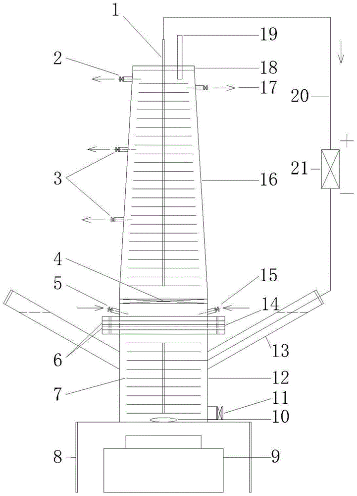
[0031] The volume ratio of the cathode chamber 16 and the anode chamber 12 in this embodiment is 2:1, and both the cathode electrode 1 and the anode electrode 7 are graphite fiber brushes.

[0032] The cathode chamber 16 in this embodiment is a truncated cone with a large lower surface, and the ratio of the area of ​​the lower surface to the area of ​​the upper surface is 1.5:1.

[0033] The mud inlet 13 of the anode chamber in this embodiment forms an angle of 45° with the horizontal line, and the liquid level of the anolyte therein is higher than the cation exchange membrane.

[0034] In this embodiment, the backflow inlet 5 and the water inlet 15 form an angle of 30° with the horizontal line.

[0035] The load 21 referred to in this embodiment refers to a resistance box set to 1000 ohms.

[0036] The sludge ...

Embodiment 2

[0041] The anaerobic biological cathode microbial fuel cell of the present invention is used to treat steel rolling wastewater containing nitrate.

[0042] Steel rolling wastewater contains a large amount of nitrate. At present, most enterprises adopt reverse osmosis process for wastewater reuse process. The reverse osmosis process will produce about 30% concentrated brine, and the nitrate in the concentrated brine will be concentrated 3-4 times, reaching 50- 100mg / L, and very little carbon source.

[0043] The volume ratio of the cathode chamber 16 and the anode chamber 12 in this embodiment is 3:1, and both the cathode electrode 1 and the anode electrode 7 are carbon felts.

[0044] The cathode chamber 16 in this embodiment is a truncated cone with a large lower surface, and the ratio of the area of ​​the lower surface to the area of ​​the upper surface is 2:1.

[0045] The mud inlet 13 of the anode chamber in this embodiment forms an angle of 45° with the horizontal line, an...

Embodiment 3

[0053] The simulated wastewater containing dichromate is treated by using the anaerobic biocathode microbial fuel cell of the invention.

[0054] Chromium-containing waste water is produced in mineral processing, smelting, electroplating, printing and dyeing, leather and inorganic salt production and other industrial processes. Among the chromium compounds, hexavalent chromium is the most toxic, followed by trivalent chromium, divalent chromium and chromium itself have little or no toxicity.

[0055] The volume ratio of the cathode chamber 16 and the anode chamber 12 in this embodiment is 5:1, and both the cathode electrode 1 and the anode electrode 7 are made of carbon cloth.

[0056] The cathode chamber 16 in this embodiment is a truncated cone with a relatively large lower surface, and the ratio of the area of ​​the lower surface to the area of ​​the upper surface is 3:1.

[0057] The mud inlet 13 of the anode chamber in this embodiment forms an angle of 45° with the horiz...


PUM

PropertyMeasurementUnit
pore sizeaaaaaaaaaa

Abstract

The invention relates to a continuous-flow anaerobic biological cathode microbial fuel cell, which is characterized in that a cathode chamber (16), an anode chamber (12) and a cation exchange membrane (14) are in sealed connection with a flange (6); the volume ratio of the cathode chamber (16) to the anode chamber (12) is (2-5):1; a water inlet (15), a backflow inlet (5), an intermediate water outlet (3), a water outlet (2) and a backflow outlet (17) are arranged in the cathode chamber (16); a detachable perforated clapboard (4), a cathode electrode (1) and a reference electrode (19) are arranged in the cathode chamber (16); the cathode electrode (1) and a load (21) are connected with a mud inlet (13) of the anode chamber (12) through an external conductor wire (20); an anode electrode (7) and a stirrer (10) are arranged in the anode chamber (12); a magnetic stirring device (9) is arranged on the lower part of the anode chamber (12); and a mud discharging hole (11) is also arranged in the anode chamber (12). The continuous-flow anaerobic biological cathode microbial fuel cell disclosed by the invention is capable of removing oxidative pollutants in water and organic matters in excess sludge simultaneously; electricity generation is carried out synchronously; and the continuous-flow anaerobic biological cathode microbial fuel cell is widely applied to continuous removal of oxidative pollutants in underground water, electroplating wastewater, rolling wastewater, beneficiation wastewater and the like.

Description

technical field [0001] The invention relates to a continuous flow anaerobic biocathode microbial fuel cell. Specifically, it is a continuous flow anaerobic biocathode microbial fuel cell for synchronously treating excess sludge and oxidative pollutants in water. It belongs to the field of environmental protection technology and new energy. Background technique [0002] The content of organic matter in urban sewage plant sludge is about 10 times that of urban sewage, accounting for more than 60% of the total, and easily degradable organic matter is also more than 40%, which is the main factor affecting the stability of sludge. Sludge is rich in organic matter, such as protein, polysaccharides and fats, and is a potential biofuel. Sludge treatment costs account for 25% to 60% of the total operating costs of sewage treatment plants. Sludge treatment has become a bottleneck problem restricting the development of sewage treatment. A microbial fuel cell (MFC) is an electrochemi...

Claims


Application Information

Patent Timeline
Patent Type & Authority Patents(China)
IPC IPC(8): H01M8/16H01M8/04276C02F3/28C02F11/04H01M8/023
CPCC02F3/28C02F11/04H01M8/04H01M8/04291H01M8/16Y02E60/50
Inventor 张志强顾早立郝小旋夏四清
Owner 温州嘉伟环保科技有限公司
Why Eureka
Try Eureka