
A method for additive manufacturing of copper alloy laser-cold metal transition compound heat source

A technology of cold metal transition and composite heat source, applied in manufacturing tools, laser welding equipment, metal processing equipment, etc., can solve problems such as large thermal expansion coefficient and shrinkage rate, small surface tension of copper alloy, laser damage, etc., and achieve low equipment cost , improve the absorption rate, reduce the effect of requirements

Inactive Publication Date: 2017-02-01
JIANGSU UNIV OF SCI & TECH
View PDF5 Cites 0 Cited by
  • Summary
  • Abstract
  • Description
  • Claims
  • Application Information

AI Technical Summary

Problems solved by technology

Compared with stainless steel, high-strength steel, etc., copper alloy has strong reflection ability to light and heat, high thermal conductivity, and is difficult to melt; it is easier to oxidize and form pores; it has a large thermal expansion coefficient and shrinkage rate, and is prone to cracks; in addition, copper alloy The surface tension is small and forming is difficult. Therefore, the steel welding process specifications (process parameters, protection measures, etc.) are not suitable for copper alloy laser + CMT hybrid welding
For example, the lack of additional gas protection for the above patent scheme, the protection effect is poor, and it is easy to cause oxidation and pores; and the laser is perpendicular to the weldment, which is easy to cause damage to the laser

Method used


Image

  • A method for additive manufacturing of copper alloy laser-cold metal transition compound heat source
  • A method for additive manufacturing of copper alloy laser-cold metal transition compound heat source
  • A method for additive manufacturing of copper alloy laser-cold metal transition compound heat source

Examples


example 1

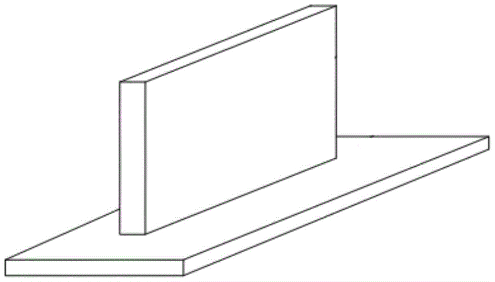
[0030]Such as figure 2 The size of the copper alloy component shown is 100mm×10mm×40mm, and it is composed of 40 layers of surfacing welding layers, each layer height is 1mm, and each layer of welding seam is composed of 7 welding seams.

[0031] Welding process parameters: welding wire 2 uses ERCuSi-A with a diameter of 1.2mm, welding current is 80A, welding voltage is 9.9V, laser power is 500W, wire feeding speed is 3.7m / min, welding speed is 1.2m / min, CMT shielding gas The flow rate is 16L / min, and the flow rate of the protective gas ejected from the protective gas nozzle 4 is 18L / min.

[0032] The specific plan is as follows:

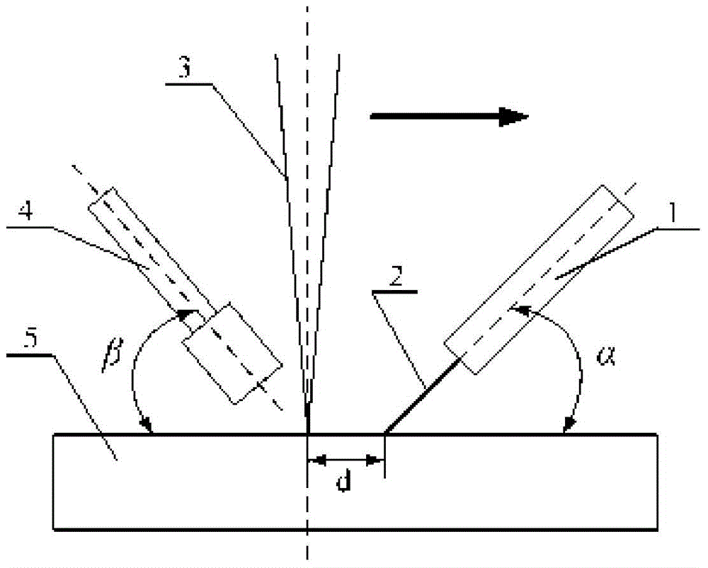
[0033] (1) Fix the laser welding torch 3, CMT welding torch 1, and shielding gas nozzle 4, the cold metal transition arc is in front, the laser is behind, the distance between the light filaments is 1mm, the defocus is 3mm, and the angle between CMT welding torch 1 and the horizontal plane is 70° , the angle between the laser input and the normal...

example 2

[0041] Such as figure 2 As shown, the copper alloy component is 100mm×15mm×60mm, and the height of each layer of surfacing welding is 1.2mm. It is composed of 50 layers of welding, and each layer of welding seam is composed of 10 welding seams.

[0042] Welding process parameters: welding wire 2 uses ERCuSi-A with a diameter of 1mm, welding current is 50A, welding voltage is 10V, laser power is 400W, wire feeding speed is 2.5m / min, welding speed is 1m / min, CMT shielding gas flow rate is 15L / min, the auxiliary protective gas flow rate is 15L / min.

[0043] The specific implementation plan is as follows:

[0044] (1) Fix the laser welding torch 3, CMT welding torch 1, and shielding gas nozzle 4, the cold metal transition arc is in front, the laser is behind, the distance between the light filaments is 1mm, the defocus is 2mm, and the angle between CMT welding torch 1 and the horizontal plane is 60° , the angle between the laser input and the normal direction of the substrate 5...

example 3

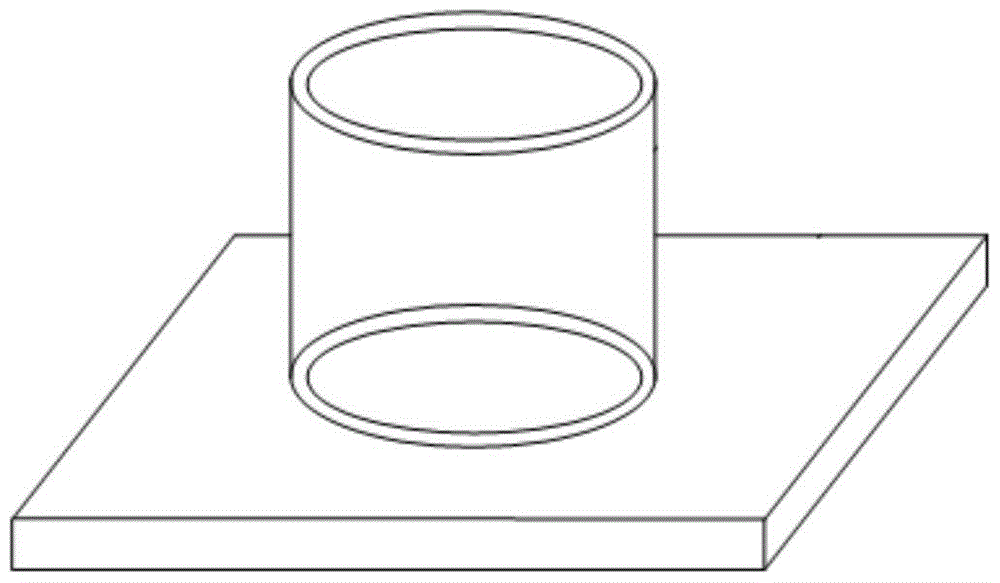
[0052] Such as image 3 As shown, the copper alloy component is 90 mm high, 20 mm thick, and 180 mm in inner diameter. It is composed of 60 layers of surfacing welding layers, each layer is 1.5 mm in height, and each layer is composed of 10 layers.

[0053] Welding process parameters: welding wire 2 uses ERCuSi-A with a diameter of 2mm, welding current is 150A, welding voltage is 17V, laser power is 800W, wire feeding speed is 6m / min, welding speed is 2m / min, CMT shielding gas flow rate is 25L / min, the auxiliary protective gas flow rate is 25L / min.

[0054] The specific implementation plan is as follows:

[0055] (1) Fix the laser welding torch 3, the CMT welding torch 1, and the shielding gas nozzle 4. The cold metal transition arc is in the front, the laser is behind, the distance between the light filaments is 3mm, the defocus is 0mm, the angle between the laser and the substrate 5 is 15°, the angle between the CMT welding torch 1 and the substrate 5 is 70°, and the angl...


PUM

PropertyMeasurementUnit
diameteraaaaaaaaaa

Abstract

The invention discloses a copper alloy laser-cold metal transition compound heat source material increase manufacturing method. The method comprises the steps that laser and a cold metal transition arc are adopted as a compound heat source, copper alloy welding wires are molten for bead welding, and copper alloy products are formed by stacking bead welding layers one by one. According to the copper alloy laser-cold metal transition compound heat source material increase manufacturing method, due to the effective coupling of the laser and the CMT electric arc, the problem that mucous threads, top threads and layers are not completely fused during laser material increase manufacturing in a copper alloy wire feeding mode is solved, meanwhile, the defects that the heat source moving speed is low and the heat affected zone is wide during TIG arc material increase manufacturing are overcome, the compound heat source is high in moving speed, the welding process is stable, forming is good, the quality is high, the machining efficiency is remarkably improved, and the technological reliability is improved; in addition, due to the fact that the laser is not used for melting welding wires and the laser absorptivity of copper alloy is improved when the arc is preheated, the requirement of the technology for the laser power is lowered.

Description

technical field [0001] The invention relates to a copper alloy welding method, in particular to a copper alloy laser-cold metal transition composite heat source additive manufacturing method. Background technique [0002] At present, copper / copper alloy products / parts are mainly manufactured by casting and mechanical processing. Although the mechanical processing method has high processing precision, it has problems such as low material utilization rate, complicated procedures, long production cycle, and high manufacturing cost; while the casting method is It is easy to produce structural defects and affect subsequent production processes such as welding. Therefore, the current two manufacturing processes cannot meet the progress requirements of rapid development and mass production of new products. Metal additive manufacturing technology is driven by CAD software, using a heat source to melt metal materials, layer by layer deposition and superimposition to form parts, which...

Claims


Application Information

Patent Timeline
Patent Type & Authority Patents(China)
IPC IPC(8): B23K26/348
CPCB23K26/348B23K2103/12
Inventor 胥国祥胡庆贤刘文张卫卫刘朋
Owner JIANGSU UNIV OF SCI & TECH
Learn More