A tunable optical micro-cavity Raman laser and a tunable optical micro-cavity doped laser

A Raman laser and optical microcavity technology, applied in the field of lasers, can solve the problems of inability to develop and apply large-scale integration, high relative intensity noise, and high threshold, and achieve large-scale development and application, low relative intensity noise, Simple effect of tuning mechanism

Inactive Publication Date: 2015-09-23
ANHUI UNIVERSITY
View PDF8 Cites 16 Cited by
  • Summary
  • Abstract
  • Description
  • Claims
  • Application Information

AI Technical Summary

Problems solved by technology

The problems of the tunable Raman fiber laser with this structure are: (1) use a long fiber as the nonlinear gain medium, and the volume is relatively large; (2) the resonator adopts multiple pairs of fiber Bragg gratings (FBG) Form, the conventional FBG reflection bandwidth is narrow, which limits the conversion efficiency of the laser; (3) It cannot be well integrated with the chip of the communication system, and cannot be developed and applied on a large scale; (4) The Q value is low, and the laser The conversion efficiency is low, the threshold is high, and the relative intensity noise is high; (5) The tuning mechanism of the laser usually adopts the form of filter tuning and thermal tuning. Filter tuning requires the introduction of additional optical devices, which increases the complexity of the system degree and insertion loss, which increases the cost of the laser; for thermal tuning, a large area of ​​heating is required, and the heating efficiency is low
The problems of the tunable doped fiber laser with this structure are: (1) the long fiber is used as the gain medium, and the volume is relatively large, which limits its application in occasions with special requirements for size, and the application is inconvenient; (2) ) cannot be well integrated with the chips of modern communication systems, and it is difficult to

Method used


Image

  • A tunable optical micro-cavity Raman laser and a tunable optical micro-cavity doped laser
  • A tunable optical micro-cavity Raman laser and a tunable optical micro-cavity doped laser
  • A tunable optical micro-cavity Raman laser and a tunable optical micro-cavity doped laser

Examples


Embodiment Construction

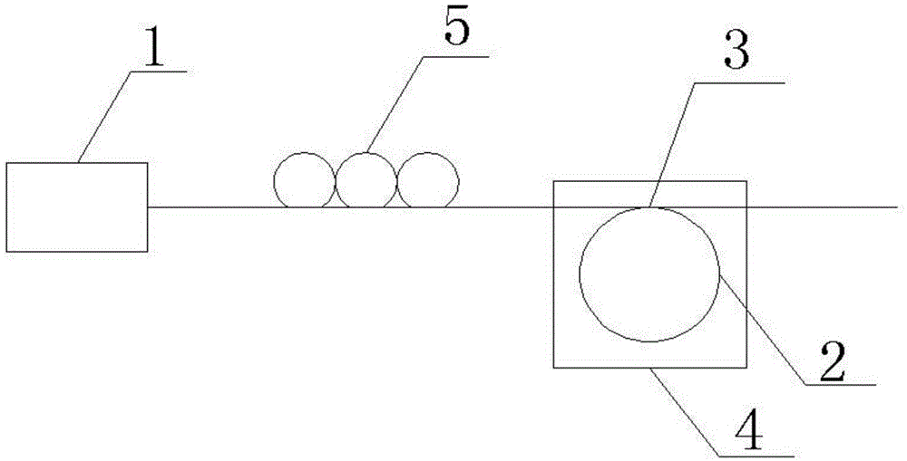
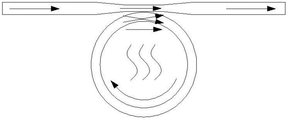
[0042] Micro-annular optical micro-cavity tuning principle

[0043] The resonant wavelength of the microring optical microcavity can be written in the form of Equation 1

[0044] λ M = 2 πRn e f f M - - - ( 1 )

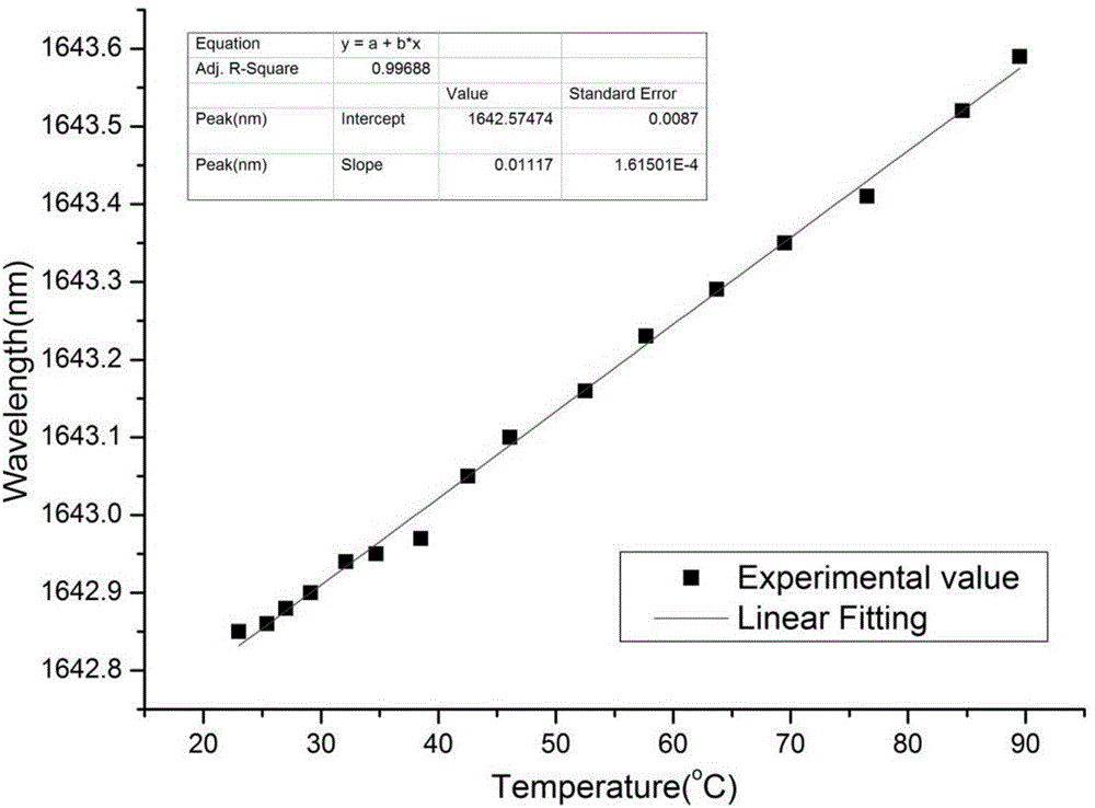
[0045] lambda M is the wavelength in vacuum of the laser in the M (M is a positive integer) order resonance mode, R is the radius of the microdisk, n eff is the effective refractive index of the whispering gallery mode. By changing the resonant wavelength condition in Equation 1, the resonant output wavelength in the gain spectrum can be changed to realize the tuning of the output wavelength of the laser. When the temperature of the microcavity changes, both the microcavity volum...


PUM


Abstract

The invention relates to the field of lasers and specifically relates to a tunable optical micro-cavity Raman laser and a tunable optical micro-cavity doped laser. The tunable optical micro-cavity Raman laser comprises a first pump source, an optical micro-cavity, a coupling device and a temperature control apparatus. The first pump source and the optical micro-cavity are connected via the coupling device, and the optical micro-cavity is in a temperature control scope of the temperature control apparatus. The tunable optical micro-cavity doped laser comprises a second pump source generating 980nm or 1480nm pump light, a doped optical micro-cavity, a coupling device, a wavelength division multiplexer and a temperature control apparatus. The second pump source, the doped optical micro-cavity and the wavelength division multiplexer are connected through the coupling device, and the doped optical micro-cavity is in the temperature control scope of the temperature control apparatus. According to the invention, the structure is simple; the size is small; the Q-value is high; and subsequent integration application is provided with convenience. Tuning of wavelengths of emitting laser is realized through controlling of the temperature of the micro-cavity. The tuning mechanism is simple, convenient and efficient.

Description

technical field [0001] The invention relates to the field of lasers, in particular to a tunable optical microcavity Raman laser and a tunable optical microcavity doping laser. Background technique [0002] Tunable fiber lasers are key components of modern fiber optic communication systems. They have natural compatibility with optical fibers and high-quality beam quality. They are also commonly used in the fields of medicine, fiber optic sensing and spectral analysis. With the increase of communication capacity and the development of optical fiber manufacturing technology, tunable fiber laser has been paid more and more attention and gradually applied. However, in practical applications, it is found that various types of tunable fiber lasers currently on the market have some insurmountable problems. [0003] The structure of the existing tunable Raman fiber laser mainly includes a pump source, a resonator, a gain medium and an acousto-optic tunable filter. Generally, a grati...

Claims


Application Information

Patent Timeline
IPC IPC(8): H01S3/30H01S3/108H01S3/08
Inventor 吕亮杨兰俞本立王德辉周俊峰向荣殷光军
Owner ANHUI UNIVERSITY
Why Eureka
Try Eureka