Well cementation cement system for in-situ combustion

A technology of cementing and burning oil layers, which is applied in solid waste management, drilling composition, sustainable waste treatment, etc., can solve the problems of resistance to ultra-high temperature conditions, stability and uniformity of cement stones that are difficult to achieve in burning oil layers in thermal recovery wells. Qualitative damage, shortening the production life of heavy oil thermal recovery wells, etc., to achieve the effects of controllable thickening time, good cementing quality, and safe construction

Active Publication Date: 2015-11-04
四川凯尔油气田技术服务有限公司
View PDF4 Cites 10 Cited by
  • Summary
  • Abstract
  • Description
  • Claims
  • Application Information

AI Technical Summary

Problems solved by technology

During thermal oil recovery, the temperature of the incinerated oil layer is as high as 600°C to 700°C. During the exploitation of the incinerated oil layer, the wellbore will be subjected to repeated periodic high temperatures, which will lead to the decline of the compressive strength of the cement sheath at high temperatures, the increase of the permeability, and the stability of the cement stone. And the homogeneity is destroyed, and the production life of the heavy oil thermal recovery well is directly shortened after the wellbore is damaged, which reduces the oil recovery efficiency
[0003] There are certain difficulties in the formulation design of cementing cement slurry for thermal recovery well combustion oil layers. The existing conventional cement slurry formulations are difficult to meet the ultra-high temperature resistance conditions of thermal recovery well combustion oil formations. The currently developed aluminophosphate cementing cement The slurry system is easily polluted by Portland cement, which leads to harsh construction conditions on site. Therefore, it is necessary to develop a cementing slurry system with strong on-site adaptability and easy and safe construction for the cementing of incinerated oil layers.

Method used


Image

  • Well cementation cement system for in-situ combustion
  • Well cementation cement system for in-situ combustion

Examples


Embodiment 1

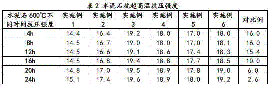
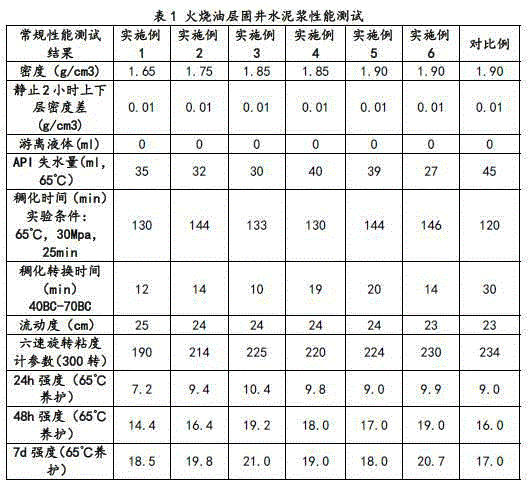
[0028] Cementing cement system for burning oil layers: Weigh each component according to the following weight components: 50 parts of G grade oil well cement; 50 parts of CA50-G6 aluminate cement, 20 parts of fly ash, 20 parts of quartz sand, 14 parts of micro silicon, 1.4 parts of sodium lignosulfonate, 0.6 parts of retarder and 1.6 parts of fluid loss reducer, wherein the retarder is calcium hydrogen phosphate, and the fluid loss reducer is polyvinyl alcohol.

[0029] In this embodiment, the quartz sand is sieved by 0.15 mm, and the sieved quartz sand is selected.

[0030] Cementing cement slurry system for burning oil layers: Add 97 parts of tap water to the above cement system. The cement slurry was prepared according to the oil and gas well cementing cement slurry test standard ISO 10426-2003.

Embodiment 2

[0032] Cementing cement system for burning oil layers: 50 parts of G grade oil well cement, 50 parts of CA50-G6 aluminate cement, 20 parts of fly ash, 20 parts of quartz sand, 14 parts of micro silicon, 1.4 parts of sodium lignosulfonate , 6 parts of iron ore powder, 0.8 parts of retarder and 1.7 parts of fluid loss reducer, wherein the retarder is sodium citrate, and the fluid loss reducer is AM / AA / AMPS copolymer.

[0033] In this embodiment, the quartz sand is sieved by 0.15 mm, and the sieved quartz sand is selected.

[0034] The particle size of the hematite powder is 200 mesh to 500 mesh, and the density is 4.5 g / cm 3 .

[0035] Cementing cement slurry system for burning oil layers: Add 97 parts of tap water to the above cement system. The cement slurry was prepared according to the oil and gas well cementing cement slurry test standard ISO 10426-2003.

Embodiment 3

[0037] Cementing cement system for burning oil layers: 50 parts of G grade oil well cement, 50 parts of CA50-G6 aluminate cement, 20 parts of fly ash, 20 parts of quartz sand, 14 parts of micro silicon, 1.4 parts of sodium lignosulfonate , 12 parts of iron ore powder, 0.9 parts of retarder and 1.8 parts of fluid loss reducer, the retarder is D-sodium gluconate, and the fluid loss reducer is AM / AA / AMPS copolymer.

[0038] In this embodiment, the quartz sand is sieved by 0.15 mm, and the sieved quartz sand is selected.

[0039] The particle size of the hematite powder is 500 mesh to 800 mesh, and the density is 4.8g / cm 3 .

[0040] Cementing cement slurry system for burning oil layers: Add 97 parts of tap water to the above cement system. The cement slurry was prepared according to the oil and gas well cementing cement slurry test standard ISO 10426-2003.


PUM

PropertyMeasurementUnit
particle size (mesh)aaaaaaaaaa
densityaaaaaaaaaa
particle size (mesh)aaaaaaaaaa

Abstract

The invention discloses a well cementation cement system for in-situ combustion. The well cementation cement system for the in-situ combustion comprises, by weight, 50 parts of G-class oil well cement, 50 parts of aluminate cement, 20 parts of coal ash, 20 parts of quartz sand, 14 parts of micro silicon, 1.4 parts of sodium lignin sulfonate, 0-15 parts of iron ore powder, 0.6-1 part of retarder and 1.6-2 parts of fluid loss agents; the retarder adopts one of calcium hydrophosphate, sodium citrate and D-sodium gluconate or a composition of the calcium hydrophosphate, the sodium citrate and the D-sodium gluconate, and the fluid loss agents adopt one of polyvinyl alcohol, AM/AA/AMPS copolymers and sodium polystyrene sulfonate or a composition of the polyvinyl alcohol, the AM/AA/AMPS copolymers and the sodium polystyrene sulfonate. According to the well cementation cement system for the in-situ combustion, the requirements that the in-situ combustion reaches to temperature up to 600 DEG C to 700 DEG C in oil thermal recovery can be met, the advantages of being high in compression resistance strength, low in permeability and good in set cement stability and homogeneity at 600 DEG C to 700 DEG C are achieved, and the site construction requirements can be met.

Description

technical field [0001] The invention relates to a cement system for oilfield drilling and cementing, in particular to a cementing cement system for burning oil layers, and belongs to the technical field of drilling and production. Background technique [0002] At present, heavy oil recovery in oil fields is mainly based on thermal oil recovery. During thermal oil recovery, the temperature of the incinerated oil layer is as high as 600°C to 700°C. During the exploitation of the incinerated oil layer, the wellbore will be subjected to repeated periodic high temperatures, which will lead to the decline of the compressive strength of the cement sheath at high temperatures, the increase of the permeability, and the stability of the cement stone. And the homogeneity is destroyed, and the production life of the heavy oil thermal recovery well is directly shortened after the wellbore is damaged, which makes the oil recovery efficiency drop. [0003] There are certain difficulties i...

Claims


Application Information

Patent Timeline
Patent Type & Authority Applications(China)
IPC IPC(8): C09K8/487C04B28/06C04B18/08C04B14/06C04B24/18C04B18/12C04B103/22
CPCC04B28/06C04B2103/0053C04B2103/22C04B2111/00724C09K8/487C04B7/02C04B18/08C04B14/06C04B24/18C04B18/12Y02W30/91
Inventor 邓天东
Owner 四川凯尔油气田技术服务有限公司
Why Eureka
Try Eureka