Eureka AIR delivers breakthrough ideas for toughest innovation challenges, trusted by R&D personnel around the world.

Annular yoke armature winding high-power-density mixed excitation permanent magnet motor

A high power density, permanent magnet motor technology, applied in the shape/style/structure of winding conductors, synchronous machine parts, magnetic circuit static parts, etc., can solve the damage of permanent magnet mechanical structure and the cost of motor power inverter circuit The problems of high cost and high motor cost can eliminate mechanical stress damage, avoid magnetic performance degradation, and save material consumption.

Active Publication Date: 2015-12-30
SHANDONG UNIV
View PDF7 Cites 6 Cited by
  • Summary
  • Abstract
  • Description
  • Claims
  • Application Information

AI Technical Summary

Problems solved by technology

[0006] In addition, there are single-phase permanent magnet motors. Single-phase permanent magnet motors need to be started and operated with supporting capacitors, which are bulky, high in cost, and have low overall operating efficiency and power factor.
[0007] Due to the fixed magnetomotive force of the permanent magnet in the existing permanent magnet motor, the main magnetic flux of the motor cannot be adjusted, resulting in a narrow constant power operating range and a wide range of speed regulation. In addition, the motor winding is generally 3 phases, the number of stator slots is large, and the winding off-line process Complicated; the permanent magnets of most existing permanent magnet motors are located on the rotor and rotate with the rotor during operation. The permanent magnets need to be fixed by special procedures, and the manufacturing cost is high. Especially when the motor speed is high, it is more difficult to fix the permanent magnets. Located on the rotor, it is difficult to dissipate heat during operation. The temperature rise and the vibration caused by the rotation of the rotor will cause damage to the mechanical structure of the permanent magnet and irreversible demagnetization; the existing permanent magnet motor is generally three-phase, and the power inverter circuit of the motor is required to be at least Six power switching devices, such as IGBT or MOSFET, and the corresponding driving circuit and protection circuit for driving the power switching device make the cost of the motor power inverter circuit quite high, even reaching two to three times the cost of the motor itself. The increase in the number of power switching devices increases the complexity of the control circuit, the possibility of device failure increases, and the reliability of the system decreases during operation
[0008] In view of the shortcomings of the existing permanent magnet motors that the excitation magnetic potential cannot be adjusted, relevant scholars have proposed some hybrid excitation structure motors. This type of hybrid excitation structure motors can be divided into two types in terms of excitation methods. One is the permanent magnet magnetic potential and the excitation winding. Magnetic potential series structure, this type of structure is not widely used because the excitation flux needs to pass through the permanent magnet, the excitation current is large, the excitation loss is high, and there is a risk of irreversible demagnetization of the permanent magnet; the other type is the permanent magnet magnetic potential The structure connected in parallel with the magnetic potential of the excitation winding, this type of structure generally adopts the stator permanent magnet type, the permanent magnet is located on the stator, and the magnetic field is adjusted by adjusting the current of the excitation winding. More, making the structure of the motor complex, sometimes there are multiple sets of windings in one slot or there are both phase windings and excitation windings, phase-to-phase insulation needs to be added in the slot, the winding process is complicated, the slot utilization rate is low, and , it is necessary to add the excitation slot, the mechanical structure of the motor is seriously fragmented, it is difficult to assemble and fix, the processing technology is complicated, and the cost of the motor is high
More importantly, after adding the field winding, at least one more power switching device needs to be added to control the current of the field winding, which further increases the cost of the power circuit. Moreover, the magnetic flux generated by the field winding and the main flux share the main magnetic field. circuit and main air gap, the excitation effect is limited by other design parameters of the motor. Once the motor is manufactured, the excitation effect can only be controlled by adjusting the excitation current, and the excitation flux cannot be controlled by separately designing the excitation magnetic circuit. Therefore, it is necessary to seek a body A hybrid excitation permanent magnet motor with simple structure, low cost, flexible magnetic field adjustment function but a small number of power switching devices, and low cost controller and power circuit is very important. Function but the number of power switching devices is small, the hybrid excitation permanent magnet motor with low cost of controller and power circuit is very important
[0009] In addition, the existing permanent magnet motors mostly use distributed windings or concentrated windings spanning multiple pole pitches, which generally have long winding ends, a large amount of copper, high manufacturing costs, high copper consumption during motor operation, and low efficiency. Disadvantages, especially for motors with large outer diameter and small axial length, that is, a large ratio of diameter to length, this disadvantage is particularly prominent, and special winding coil connection methods are required to reduce the winding end and reduce the use of Copper, improving the efficiency of motor operation

Method used


Image

  • Annular yoke armature winding high-power-density mixed excitation permanent magnet motor
  • Annular yoke armature winding high-power-density mixed excitation permanent magnet motor
  • Annular yoke armature winding high-power-density mixed excitation permanent magnet motor

Examples


Embodiment 1

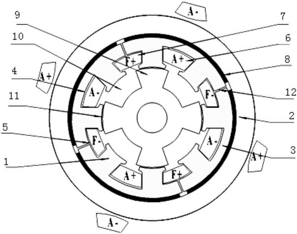
[0068] like image 3 As shown, the number of stator teeth of the motor is 8, the number of rotor teeth is 4, and the number of permanent magnet blocks is 4. This embodiment includes a stator, a rotor, a main air gap and an additional air gap. The stator includes a stator core, a permanent magnet and a stator slot, and the stator The iron core includes stator teeth 1, stator back yoke 2 and stator slot yoke 3. The stator core is made of ferromagnetic material with high magnetic permeability. The stator core is provided with stator slots. The stator slots include armature slots 4 and excitation slots 5. , the armature slots 4 and the excitation slots 5 are alternately arranged at intervals, and the armature winding 6 is placed in the armature slot 4, and the armature winding 6 penetrates from one armature slot 4, and then along the outer surface of the stator back yoke 2 in the direction of the outer diameter Pass out to form a coil, the armature winding 6 is wound around the st...

Embodiment 2

[0070] like Figure 4 As shown, the number of stator teeth of the motor is 8, the number of rotor teeth is 4, and the number of permanent magnet blocks is 16. This embodiment includes a stator, a rotor, a main air gap and an additional air gap. The stator includes a stator core, a permanent magnet and a stator slot, and the stator The iron core includes stator teeth 1, stator back yoke 2 and stator slot yoke 3. The stator core is made of ferromagnetic material with high magnetic permeability. The stator core is provided with stator slots. The stator slots include armature slots 4 and excitation slots 5. , the armature slots 4 and the excitation slots 5 are alternately arranged at intervals, and the armature winding 6 is placed in the armature slot 4, and the armature winding 6 penetrates from one armature slot 4, and then along the outer surface of the stator back yoke 2 in the direction of the outer diameter Pass out to form a coil, the armature winding 6 is wound around the ...


PUM


Abstract

The invention discloses an annular yoke armature winding high-power-density mixed excitation permanent magnet motor. A stator groove of the motor comprises armature grooves and excitation grooves; the armature grooves and the excitation grooves are alternatively arranged at intervals in the peripheral direction; a set of armature winding is arranged in the armature grooves and is electrified with alternating current; a set of exciting winding is arranged in two adjacent excitation grooves in a surrounding manner and is electrified with direct current; a main air gap is arranged between each stator tooth and the corresponding rotor tooth; a stator groove yoke above the grooves of the exciting winding is disconnected in the radial direction and is provided with an additional air gap; an armature current magnetic field, an exciting current magnetic field and magnetic fields generated by permanent fields interact to change magnetic flux on the stator teeth, and magnetic resistance between a stator and a rotor changes to generate torque. The annular yoke armature winding high-power-density mixed excitation permanent magnet motor effectively decreases the number of power switching elements, reduces the probability that the power switching elements in a motor control circuit break down, and is improved in reliability.

Description

technical field [0001] The invention relates to a high power density hybrid excitation permanent magnet motor with an annular yoke armature winding. Background technique [0002] In recent years, with the improvement of high temperature resistance and price reduction of permanent magnet materials, permanent magnet motors have been more widely used in national defense, industrial and agricultural production, and daily life, and are moving towards high power, high performance and miniaturization. direction of development. At present, the power of permanent magnet motors ranges from a few milliwatts to several thousand kilowatts, and its application ranges from toy motors, industrial applications to large permanent magnet motors for ship traction, and has been widely used in various aspects of the national economy, daily life, military industry, and aerospace. widely used. [0003] Conventional AC permanent magnet motors are usually divided into the following categories: asyn...

Claims


Application Information

Patent Timeline
Patent Type & Authority Applications(China)
IPC IPC(8): H02K21/02H02K1/16H02K1/17H02K3/28
Inventor 王道涵
Owner SHANDONG UNIV
Why Eureka
Eureka Blog
Learn More