Large-space dirt removal device with gas-sound complex fields uniformly distributed and dirt removal method of large-space dirt removal device

A compound field and large space technology, applied in the direction of combustion method, removal of solid residue, treatment of combustion products, etc., can solve the problems of high flue gas dew point, limited sound energy, insufficient rapping force, etc., and achieve uniform distribution effect improvement , sound energy enhancement, promote the effect of descaling

Active Publication Date: 2016-01-27
NANJING CHANGRONG ACOUSTIC INC
View PDF11 Cites 2 Cited by
  • Summary
  • Abstract
  • Description
  • Claims
  • Application Information

AI Technical Summary

Problems solved by technology

[0004] There are many unsolvable problems in the steam sootblower: it is easy to cause the sootblower to be stuck in the furnace during operation, resulting in mechanical jamming, high failure rate, short service life, high energy consumption, easy to cause pipe burst accidents, and common air leakage; The moisture content in the flue gas is high, the dew point of the flue gas is high; the operating cost is high, the cost of boiler feed water and water treatment is high, and the workload of repair and maintenance is large; Inner heating surface wear
Due to the limited sound energy of the traditional sonic soot blower, the sound frequency is fixed, which is very different from the natural frequency of the ash particles, and it is not suitable for the characteristics of ash accumulation. Prevents soot build-up during its soot blowing
Mechanical and electromagnetic rapping due to insufficient rapping force and easy damage to the equipment, the descaling effect is not ideal
At present, the air distribution plate generally adopts a single-layer setting, because the optimal opening ratio and the optimal hole shape are difficult to determine, so it is difficult to achieve the ideal air distribution effect

Method used


Image

  • Large-space dirt removal device with gas-sound complex fields uniformly distributed and dirt removal method of large-space dirt removal device
  • Large-space dirt removal device with gas-sound complex fields uniformly distributed and dirt removal method of large-space dirt removal device
  • Large-space dirt removal device with gas-sound complex fields uniformly distributed and dirt removal method of large-space dirt removal device

Examples


Embodiment 1

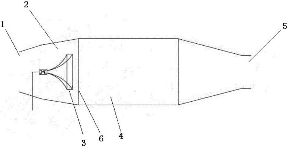
[0042] Such as figure 1 As shown, it is a schematic diagram of a large-space descaling device with an aeroacoustic composite field uniform distribution in this embodiment, including a device inlet 1, an aeroacoustic uniform field arrangement space 2, a sonic soot blowing device 3, a descaling space 4 and a device outlet 5, among which The setting method is to set the aero-acoustic equalizing arrangement space 2 behind the device entrance 1, install the sonic soot blowing device 3 in the aero-acoustic equalizing arrangement space 2, set the descaling space 4 after the aero-acoustic equalizing arrangement space 2, and set the descaling space 4 The outlet 5 of the device is installed in the rear; an aeroacoustic deflector 6 is arranged between the aeroacoustic equalization space 2 and the descaling space 4, and the sounding direction of the sonic soot blowing device 3 faces the aeroacoustic deflector 6. Depend on figure 1 It can be seen that the aeroacoustic averaging arrangemen...

Embodiment 2

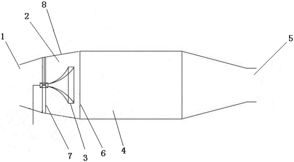
[0044] Such as figure 2 As shown, it is a further improvement on the basis of Example 1, in which an air inlet plate 7 is provided at the entrance 1 of the device, and the aeroacoustic homogenization space 2 is the air inlet plate 7, the aeroacoustic deflector 6 and the space between them. The space enclosed by the space wall 8; in order to better play the uniform distribution and reverberation effect of the aeroacoustic average field layout space, the section of the aeroacoustic average field layout space 2 along the expansion direction is set to be an isosceles trapezoid in this embodiment , wherein the space wall 8 between the aeroacoustic deflector 6 and the air inlet plate 7 is used as the waist of the isosceles trapezoidal section, the air inlet plate 7 and the aeroacoustic deflector 6 are used as the bottom of the isosceles trapezoid, and the aeroacoustic deflector 6. The corresponding side length ratio of the section formed by the air inlet plate 7 and the space wall ...

Embodiment 3

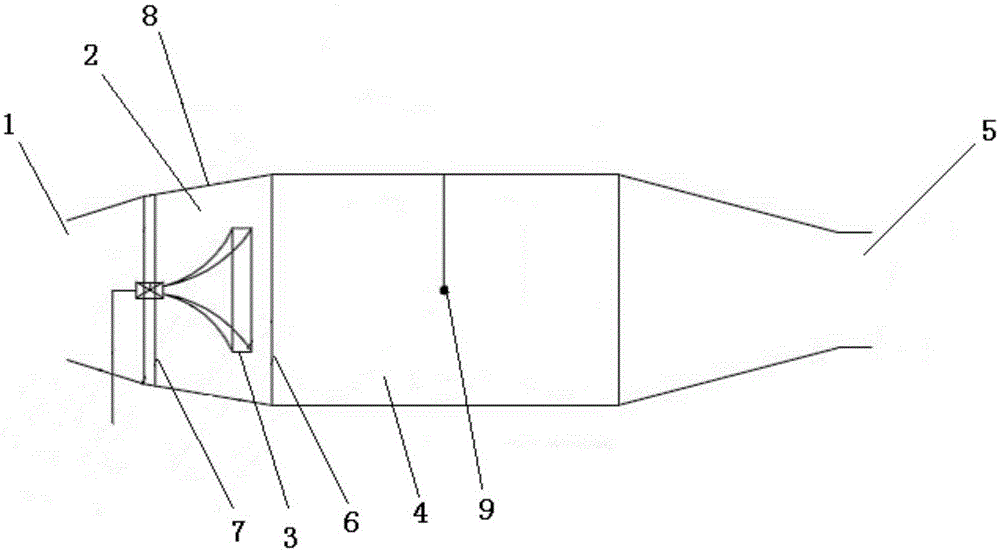
[0047] Such as image 3 As shown, as a further improvement on the basis of Example 2, an acoustic sensor 9 is provided in the descaling space 4, which can effectively monitor the sound waves passing through the descaling space 4, and timely adjust the sound wave index according to the monitoring results.

[0048] Such as Figure 4 As shown, an easy-to-fouling device 10 is also provided in the descaling space 4. The easy-to-fouling device can be installed according to needs during actual use, and can be a heat exchanger or a dust collector or other equipment. The sonic soot blowing device 3 is connected by a controller (11), a sound conduit, a sound generator and a gas pipeline, wherein the gas pipeline is used to transport the working gas of the sonic soot blowing device, and the controller (11) is used to control the sound generator During the running process, the acoustic sensor 9 is connected with the controller 11, so that the acoustic sensor 9 can feed back the sensed ac...


PUM


Abstract

The invention discloses a large-space dirt removal device with gas-sound complex fields uniformly distributed and a dirt removal method of the large-space dirt removal device. The dirt removal device comprises a device inlet, a gas-sound field uniform-distribution space, sound wave dust blowing devices, a dirt removal space and a device outlet. The gas-sound field uniform-distribution space is arranged behind the device inlet and internally provided with the sound wave dust blowing devices. The dirt removal space is arranged behind the gas-sound field uniform-distribution space. The device outlet is formed behind the dirt removal space. A gas-sound flow guide plate is arranged behind the sound wave dust blowing devices in the gas-sound field uniform-distribution space. The sound production directions of the sound wave dust blowing devices face the gas-sound flow guide plate. The dirt removal method includes the steps that after air flow is introduced into the device, the air flow is uniformly guided to form uniform air flow, then the uniform air flow and sound waves produced by the sound wave dust blowing devices are uniformized in the gas-sound field uniform-distribution space, then are uniformized and rectified through the gas-sound flow guide plate and then enter the dirt removal space, dirt removal is conducted on the device in the dirt removal space, and meanwhile local serious dirt accumulation can be prevented effectively.

Description

technical field [0001] The invention relates to a large-space descaling device and a descaling method with an aeroacoustic composite field uniform distribution and belongs to the field of environmental protection equipment. Background technique [0002] With the increasingly stringent energy conservation and emission reduction standards, the energy conservation and emission reduction work of large thermal power units has been paid more and more attention. The boiler is the core equipment of the thermal power station and one of the key links in the energy conversion of the thermal power station. The thermal efficiency of the boiler directly affects the fuel utilization rate of the thermal power station. During the production and operation of coal-fired boilers, the problem of fouling on the heating surfaces (water walls, superheaters, economizers, preheaters) and flue ducts has long plagued power production, and the thermal efficiency of coal-fired boilers cannot reach impor...

Claims


Application Information

Patent Timeline
Patent Type & Authority Applications(China)
IPC IPC(8): F23J1/00F23J3/00
Inventor 张荣初邹怡然刘宇清孙卫国王程康林云泽
Owner NANJING CHANGRONG ACOUSTIC INC
Why Eureka
Try Eureka