Flue gas pollutant cooperation removal technology based on electrolysis

A technology for pollutants and flue gas, applied in gas treatment, air quality improvement, combined devices, etc., can solve the problems of reduced reaction conversion rate, increased impeller wear, waste of power consumption, etc., to improve conversion rate, reduce energy consumption, The effect of simplifying the structure

Inactive Publication Date: 2016-02-24
WUHAN WUTUO TECH +1
View PDF3 Cites 5 Cited by
  • Summary
  • Abstract
  • Description
  • Claims
  • Application Information

AI Technical Summary

Problems solved by technology

[0004] On the one hand, there are following problems in adopting the iron filings method in the regeneration step: (1) Since the absorption liquid is acidic, the iron filings are easily corroded, resulting in a large consumption of iron filings, and the concentration of iron ions in the absorption liquid is too high, which increases the efficiency of iron removal. The cost also affects the quality of desulfurization and denitrification by-products; (2) Since the elemental iron in the iron filings is oxidized and corroded into the solution, the pH value of the absorption solution increases, resulting in the weakening of the regenerative reduction ability of the iron filings to the complexing agent
In order to ensure the denitrification efficiency, acid needs to be added to the system, resulting in a further increase in denitrification costs
(3) The consumption of iron filings is relatively large, and a large amount of elemental iron is oxidized into the absorption liquid. Since the pH value of the absorption liquid is controlled above 5.0, the absorption liquid contains a large amount of ferric hydroxide colloid (suspended matter), which will lead to circulation The wear of the impeller of the pump is increased, and it will also cause the nozzle and pipeline to block
(4) Since iron filings are filled in the closed regeneration tower, and the consumption of iron f

Method used


Image

  • Flue gas pollutant cooperation removal technology based on electrolysis
  • Flue gas pollutant cooperation removal technology based on electrolysis
  • Flue gas pollutant cooperation removal technology based on electrolysis

Examples


Embodiment Construction

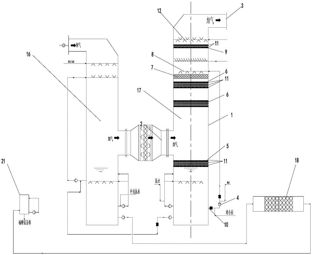
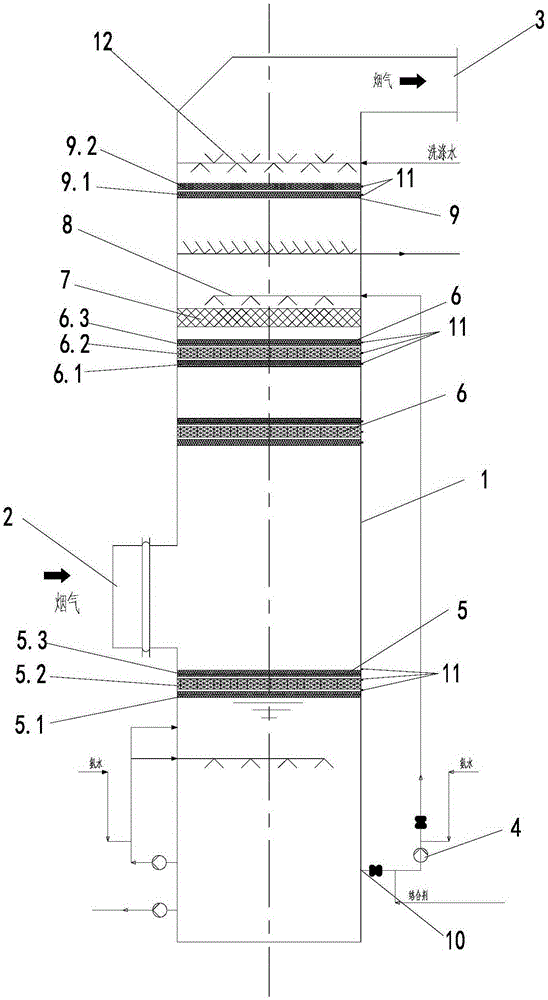
[0057] See figure 2 , The structure of the absorption tower is:

[0058] The synchronous desulfurization and denitrification reaction tower of the present invention includes a tower body 1, the top of the tower body is provided with a flue gas outlet 3, the middle of the tower body is provided with a flue gas inlet 2, and the bottom of the tower body 1 is provided with a circulating absorption liquid outlet 10, the circulating absorption liquid outlet 10 The circulating pump 4 is connected to the spray layer 8 on the upper part of the tower body, above the spray layer 8 an electrostatic defogging and reaction layer 9 is arranged in the tower body, and a washing layer is arranged above the electrostatic defogging and reaction layer 9; Below the spray layer 8 there is a packing layer 7 in the tower body, and at least one layer of absorption and electrochemical reaction layer 6 is arranged below the packing layer 7 (in this embodiment, there are two layers, two adjacent layers of ab...


PUM

PropertyMeasurementUnit
Thicknessaaaaaaaaaa
Thicknessaaaaaaaaaa
Widthaaaaaaaaaa

Abstract

The invention discloses a flue gas pollutant cooperation removal technology based on electrolysis. The problems are solved that technologies are complex, the pollutant treatment efficiency is low, investment and operation cost are high in present flue gas treatment. The technology comprises steps: flue gas is pressurized and sent to a concentration tower, a reaction is carried out, the flue gas going out from the concentration tower is sent to an absorbing tower and contacts and reacts with a circulating absorption solution sprayed from a spray layer at the upper part of the tower in a reverse manner, and the flue gas after reaction is discharged from the top of the absorbing tower; part of the concentrate at the tower bottom of the concentration tower is subjected to iron removal, then is sent to a ammonium sulfate crystallization system, the flue gas goes into the absorbing tower from a flue gas inlet at the middle part of the absorbing tower, goes through at least one absorbing and electrochemical reaction layer arranged at the upper part of the tower firstly, then contacts and reacts with a circulating absorption solution in a reverse manner, then goes through a filler layer and a spraying layer, and is discharged from a flue gas outlet. The technology is simple, the reaction efficiency is high, the operation and investment cost are low, the system land occupation area is small, and the technology is especially suitable for cooperation treatment of multiple pollutants of sulfur dioxide, nitrogen oxides, fine particles, dioxin and the like.

Description

Technical field [0001] The invention relates to a flue gas treatment process, specifically a flue gas pollutant removal process based on electrolysis, and is particularly suitable for flue gas with multiple pollutants such as sulfur dioxide, nitrogen oxides, fine particles, and dioxins. Collaborative governance. Background technique [0002] There are many types of flue gas desulfurization and denitrification technologies, and the engineering application of individual desulfurization or denitration technologies is becoming more and more perfect. However, the application of multi-pollutant cooperative control technology for flue gas is less. At present, in addition to the more mature adsorption method, other collaborative control technologies for engineering applications, especially the multi-pollutant collaborative control technology of flue gas wet method, have not been reported. Wet flue gas synchronous desulfurization and denitrification technology, such as wet ammonia-compl...

Claims


Application Information

Patent Timeline
IPC IPC(8): B01D53/75B01D53/60B01D53/70B01D50/00
CPCB01D50/00B01D53/32B01D53/60B01D53/70B01D53/74B01D53/75B01D53/78B01D53/965B01D2257/206B01D2257/302B01D2257/40B01D2258/0283B01D2259/124Y02A50/20
Inventor 吴高明王世杰韩军卫书杰
Owner WUHAN WUTUO TECH
Why Eureka
Try Eureka