Eureka AIR delivers breakthrough ideas for toughest innovation challenges, trusted by R&D personnel around the world.

Filter cloth capable of forming micro-electrolysis and application of filter cloth

A micro-electrolysis and filter cloth technology, applied in the field of filter cloth, can solve the problems of inability to apply air treatment, heavy workload, loss of function, etc.

Inactive Publication Date: 2016-03-09
ZHEJIANG JIUXIN AIR PURIFICATION TECH CO LTD
View PDF5 Cites 3 Cited by
  • Summary
  • Abstract
  • Description
  • Claims
  • Application Information

AI Technical Summary

Problems solved by technology

[0004] However, the application of traditional micro-electrolysis technology has the following deficiencies: (1) If iron-carbon bed is used as raw material, to make iron-carbon bed have the ability to decompose organic macromolecules, it is generally necessary to add hydrogen peroxide, and acidic sewage reacts with iron to form ferrous iron Ions, ferrous ions and hydrogen peroxide form Fenton's reagent, which generates hydroxyl radicals with strong oxidation properties, and degrades most of the refractory macromolecular organic substances to form small molecular organic substances, etc. However, the reaction must be under acidic conditions (2) Traditionally, the micro-electrolysis materials used in the micro-electrolysis process are generally iron filings and charcoal. Contact, it is easy to form an isolation layer so that the micro-electrolysis cannot continue and lose its function, which leads to frequent replacement of micro-electrolysis materials, which not only has a large workload and high cost, but also affects the treatment effect and efficiency of sewage; (3) The surface area of ​​traditional micro-electrolysis materials Too small also makes the sewage treatment take a long time and increases the investment cost per ton of water, which seriously affects the utilization and promotion of the micro-electrolysis process; (4) The traditional micro-electrolysis process can only be applied to sewage treatment and cannot be applied In the field of air management and other
[0005] The existing filter cloth generally includes a base cloth woven from fibers, and filter holes are arranged on the base cloth, and the structure of this filter cloth is simple, which cannot solve the problems existing in the current application of micro-electrolysis technology.

Method used


Image

  • Filter cloth capable of forming micro-electrolysis and application of filter cloth
  • Filter cloth capable of forming micro-electrolysis and application of filter cloth
  • Filter cloth capable of forming micro-electrolysis and application of filter cloth

Examples


Embodiment 1

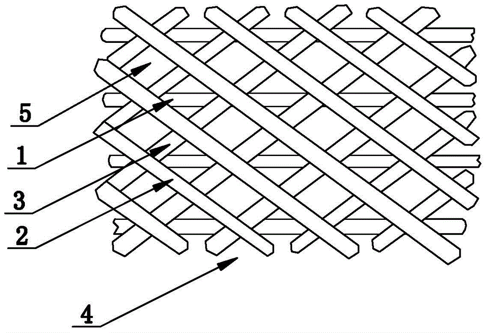
[0024] like figure 1 As shown, the filter cloth that can form micro-electrolysis is taken as 200g of carbon fiber 1, the K number of carbon fiber 1 is 1K, each of iron wire 2 and aluminum wire 3 is 100g, and the diameter of iron wire 2 and aluminum wire 3 is 0.1mm. Cloth 4, the diameter of the filter hole 5 on the base cloth 4 is 0.01mm.

[0025] Test 1: In an environment with a relative humidity of 10% and a temperature of 30°C, 8,000 volts of DC high voltage is used to energize the filter cloth in this embodiment, and keep the filter cloth moist;

[0026] With a wind speed of 1 meter per second, the polluted air containing 6,000 mg of PM2.5 particles per cubic meter is continuously passed through the above energized filter cloth, and the content of PM2.5 particles in the polluted air is reduced to 380 mg per cubic meter after being filtered by the above filter cloth. Cubic meters, the effect is remarkable;

[0027] Test 2: After the filter cloth is folded densely, the acid...

Embodiment 2

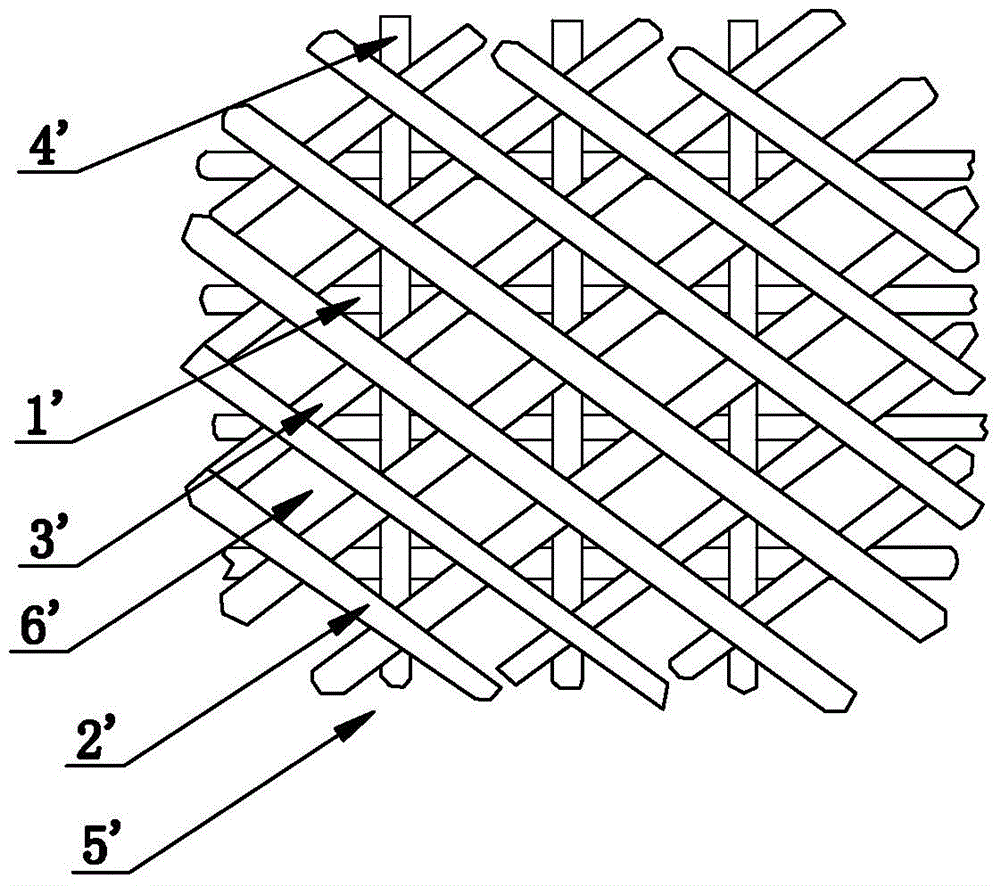
[0038] like figure 2 As shown, the filter cloth that can form micro-electrolysis, take carbon fiber 1' as 300g, the K number of carbon fiber 1' as 12K, iron wire 2', aluminum wire 3', copper wire 4' each 500g, iron wire 2', aluminum wire 3', the copper wire 4' has a diameter of 1.3 mm, and is woven into a base cloth 5', and the diameter of the filter hole 6' on the base cloth 5' is 2.5 mm.

[0039] Test 1: In an environment with a relative humidity of 30% and a temperature of 300°C, a 6,000-volt DC high voltage was used to energize the filter cloth in this embodiment and keep the filter cloth moist;

[0040] With a wind speed of 0.6 meters per second, the polluted air containing 6000 mg of PM2.5 particles per cubic meter is continuously passed through the above energized filter cloth, and the content of PM2.5 particles in the polluted air is reduced to 280 mg per cubic meter after being filtered by the above filter cloth Cubic meters, the effect is remarkable;

[0041] Test 2...

Embodiment 3

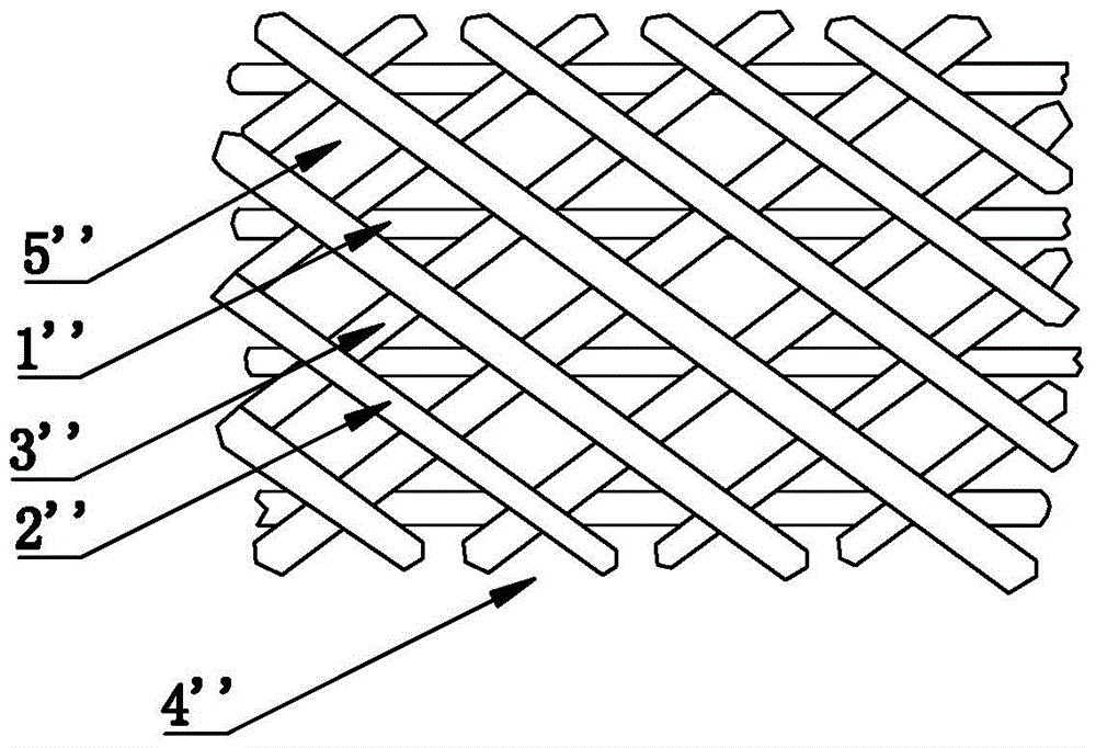
[0052] like image 3 As shown, the filter cloth that can form micro-electrolysis, take 200g of carbon fiber 1'', the K number of carbon fiber 1'' is 6K, iron wire 2'', aluminum wire 3'' each 1000g, iron wire 2'', aluminum wire 3' ' is 2.5 mm in diameter, knitted into a base cloth 4'', and the diameter of the filter hole 5'' on the base cloth 4'' is 5 mm.

[0053] Test 1: In an environment with a relative humidity of 60% and a temperature of 500°C, 10,000 volts of DC high voltage was used to energize the filter cloth in this embodiment and keep the filter cloth moist;

[0054] With a wind speed of 1.5 meters per second, the polluted air containing 6000 mg of PM2.5 particles per cubic meter is continuously passed through the above energized filter cloth, and the content of PM2.5 particles in the polluted air is reduced to 340 mg per cubic meter after being filtered by the above filter cloth Cubic meters, the effect is remarkable;

[0055] Test 2: After the filter cloth is fold...


PUM

PropertyMeasurementUnit
diameteraaaaaaaaaa
diameteraaaaaaaaaa

Abstract

The present invention relates to filter cloth capable of forming micro-electrolysis. The filter cloth comprises base cloth formed by weaving carbon fibers and at least one type of metal filaments, wherein filter holes are formed in the base cloth. The filter cloth is mainly used in the environment that the relative humidity is higher than 10% and the temperature is lower than 600 DEG C. By adopting the aforementioned technical scheme, the filter cloth can treat sewage and air, and is light in mass, small in size, low in power consumption and long in service life.

Description

technical field [0001] The invention relates to the field of filter cloth, in particular to a filter cloth capable of forming micro-electrolysis and its application. Background technique [0002] The reaction principle of micro-electrolysis: redox of electrochemical reaction. Micro-electrolysis technology mainly uses metals and metals (or non-metals) with different electrode potentials to form micro-batteries, and uses the battery effect to achieve the purpose of sewage and waste gas treatment. [0003] The traditional micro-electrolysis technology uses industrial cast iron chips as raw materials, based on the comprehensive effects of physics, chemistry and electrochemistry caused by the electrochemical principle of metal corrosion, to achieve the purpose of treating various sewage. The traditional micro-electrolysis technology mainly uses the micro-primary battery composed of the inhomogeneity of the chemical composition on the surface of cast iron chips and the inhomogene...

Claims


Application Information

Patent Timeline
Patent Type & Authority Applications(China)
IPC IPC(8): C02F1/467C02F1/463C02F1/28
Inventor 李明
Owner ZHEJIANG JIUXIN AIR PURIFICATION TECH CO LTD
Why Eureka
Eureka Blog
Learn More