

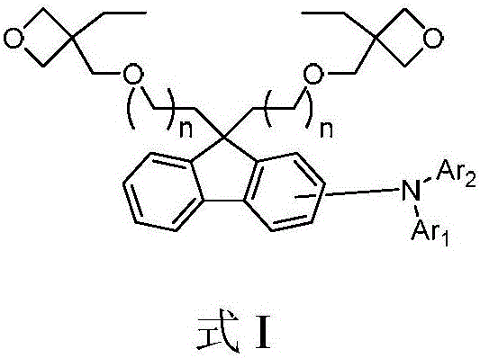
Luminescent material of a series of fluorene derivatives
A technology of light-emitting materials and light-emitting devices, which is applied in the field of materials and can solve problems such as reduced luminous efficiency, unbalanced distribution of electrons and holes, and uneven molecular weight distribution.
- Summary
- Abstract
- Description
- Claims
- Application Information
AI Technical Summary
Problems solved by technology
Method used
Image

Examples
Embodiment 1
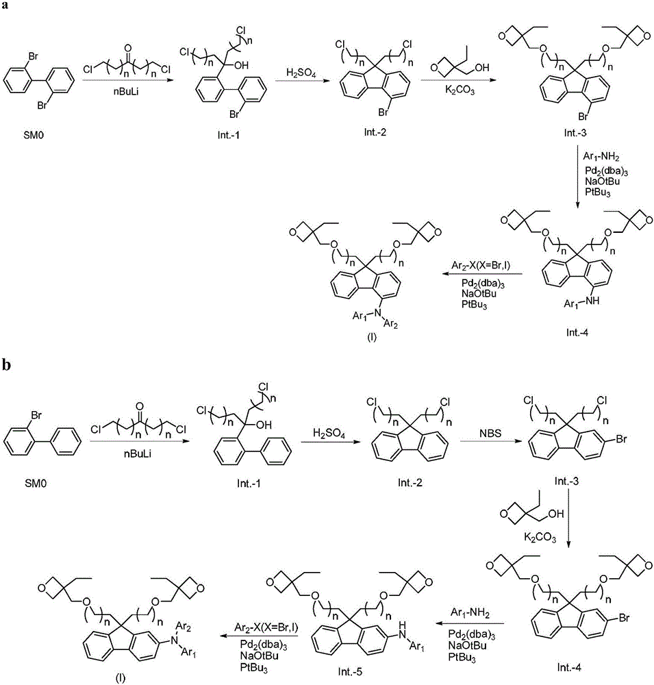
[0098] Embodiment 1, the preparation of compound 14 (n=2)
[0099]
[0100] The first step: the preparation of intermediate-1
[0101]
[0102] 20g of 2,2'-dibromobiphenyl was dissolved in 400ml of dry tetrahydrofuran, placed in a low-temperature tank under nitrogen protection, cooled to -80°C with liquid nitrogen, and slowly added dropwise to 25ml of 2.5M n-butyllithium- Hexane solution, temperature controlled and stirred at -70°C for 30 minutes, set aside.
[0103] 14g of 1,7-dichloroheptanone was dissolved in 150ml of dry tetrahydrofuran, placed in a low-temperature tank under the protection of nitrogen, cooled to -80°C with liquid nitrogen, and the reaction solution prepared above was slowly added dropwise, and the reaction was stirred for 1 hour, rose to room temperature and stirred for 30 minutes, added 100ml of saturated ammonium chloride aqueous solution to quench the reaction, extracted three times with ethyl acetate, and the organic phase was washed with anhyd...
Embodiment 2
[0123] Embodiment 2, the preparation of compound 93 (n=2)
[0124]
[0125] The first step: the preparation of intermediate-1
[0126]
[0127] 20g of 2-bromobiphenyl was dissolved in 400ml of dry tetrahydrofuran, placed in a low-temperature tank under nitrogen protection, cooled to -80°C with liquid nitrogen, and slowly added dropwise to 34.5ml of 2.5M n-butyllithium-hexane solution , temperature controlled and stirred at -70°C for 30 minutes, set aside.
[0128] Dissolve 19g of 1,7-dichloroheptanone in 150ml of dry tetrahydrofuran, place it in a low-temperature tank under the protection of nitrogen, cool down to -80°C with liquid nitrogen, slowly drop the reaction solution prepared above, and stir for 1 hour, rose to room temperature and stirred for 30 minutes, added 100ml of saturated ammonium chloride aqueous solution to quench the reaction, extracted three times with ethyl acetate, and the organic phase was washed with anhydrous Na 2 SO 4 After drying and filteri...
Embodiment 3
[0151] Embodiment 3, the preparation of compound formula 1~13, 15~87
[0152] Compounds 1-13, 15-87 can be prepared by referring to the preparation method of Example 1.
PUM
| Property | Measurement | Unit |
|---|---|---|
| thickness | aaaaa | aaaaa |
| thickness | aaaaa | aaaaa |
| thickness | aaaaa | aaaaa |
Abstract
Description
Claims
Application Information