Gas barrier film

A technology of gas barrier property and gas barrier layer, applied in the field of gas barrier film, which can solve the problems of gas barrier layer defects and inability to stably obtain high gas barrier properties

Active Publication Date: 2016-09-07
TORAY IND INC
View PDF5 Cites 6 Cited by
  • Summary
  • Abstract
  • Description
  • Claims
  • Application Information

AI Technical Summary

Problems solved by technology

[0008] However, in the method of forming a gas barrier layer mainly composed of silicon oxide by the plasma CVD method as in Patent Document 1, there is a problem in that the surface of the polymer base material

Method used


Image

  • Gas barrier film
  • Gas barrier film
  • Gas barrier film

Examples


Example Embodiment

[0132] (Example 1)

[0133] (Formation of the first layer)

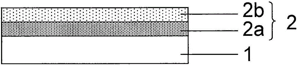
[0134] As the polymer substrate 1, a polyethylene terephthalate film having a thickness of 50 μm ("LUMIRA" (registered trademark) U48 manufactured by Toray Corporation) was used.

[0135] use Figure 5 The wound-type sputtering-chemical vapor deposition apparatus 4 (hereinafter referred to as the sputtering-CVD apparatus) shown in the winding type has a sputtering target that is a mixed sintered material formed of zinc oxide, silicon dioxide, and aluminum oxide. The sputtering electrode 11 is sputtered using argon and oxygen, and ZnO-SiO is provided as the first layer on the surface of the polymer substrate 1 2 -Al 2 O 3 Layer so that the film thickness becomes 150 nm.

[0136] The specific operation is as follows. First, a sintered sputtering target with a composition mass ratio of zinc oxide / silica / alumina of 77 / 20 / 3 is set on the sputter electrode 11 of the sputter-CVD apparatus 4. The unwinding roll 6 in the winding c...

Example Embodiment

[0144] (Example 2)

[0145] (Synthesis of polyurethane compounds with aromatic ring structure)

[0146] In a 5-liter 4-necked flask, 300 parts by mass of bisphenol A diglycidyl ether acrylic acid adduct (manufactured by Kyoeisha Chemical Co., Ltd., trade name: epoxy ester 3000A) and 710 parts by mass of ethyl acetate were added. Heat so that the internal temperature becomes 60°C. 0.2 parts by mass of di-n-butyltin dilaurate was added as a synthesis catalyst, and 200 parts by mass of dicyclohexylmethane 4,4'-diisocyanate (manufactured by Tokyo Chemical Industry Co., Ltd.) was added dropwise over 1 hour while stirring. After the completion of the dropping, the reaction was continued for 2 hours, and then 25 parts by mass of diethylene glycol (manufactured by Wako Pure Chemical Industries, Ltd.) was dropped over 1 hour. The reaction was continued for 5 hours after the dropping, and a polyurethane compound having an aromatic ring structure with a weight average molecular weight of 20...

Example Embodiment

[0156] (Example 3)

[0157] Set up ZnO-SiO as the first layer 2 -Al 2 O 3 Except that the layer had a thickness of 450 nm, the same procedure as in Example 2 was carried out to obtain a gas barrier film.


PUM

PropertyMeasurementUnit
Film thicknessaaaaaaaaaa
Thicknessaaaaaaaaaa
Thicknessaaaaaaaaaa

Abstract

The purpose of the invention is to provide a gas barrier film having excellent gas barrier characteristics. This gas barrier film includes, on at least one surface of a polymer base material, a gas barrier layer in which a first layer including zinc oxide and silicon dioxide and a second layer including a silicon compound are arranged in contact with one another in this order from the polymer base material, wherein the binding energy of the Si 2p orbit at the interface between the first layer and the second layer as measured by X-ray photoelectron spectroscopy is greater than the binding energy of the Si 2p orbit in the first layer and is smaller than the binding energy of the Si 2p orbit in the second layer.

Description

technical field [0001] The present invention relates to a gas barrier film used as a material for electronic components such as packaging materials for foods and pharmaceuticals requiring high gas barrier properties, solar cells, electronic paper, and organic electroluminescence (EL) displays. Background technique [0002] As a technique for improving the gas barrier properties of a polymer substrate, for example, it is disclosed that a gas containing silicon oxide as a main component is formed on a polymer substrate by a plasma CVD method using a vapor containing an organosilicon compound and an oxygen gas gas. , a layer containing at least one compound of carbon, hydrogen, silicon, and oxygen to improve gas barrier properties while maintaining transparency (Patent Document 1 (see claims)). In addition, as another technique for improving gas barrier properties, it is disclosed that an organic layer containing an epoxy compound and a silicon-based oxide layer formed by plasm...

Claims


Application Information

Patent Timeline
IPC IPC(8): B32B9/00B65D65/40C08J7/043C08J7/046C08J7/048
CPCC23C28/00C08J2367/02C08J2375/04C23C14/08C23C16/401C23C28/04C08J7/0423C08J7/048C08J7/043C08J7/046B32B9/04B32B9/045B32B2307/7244B32B2307/7242B32B2264/102B32B2264/10B32B2439/00B32B2457/00
Inventor 上林浩行佐竹光德永幸大
Owner TORAY IND INC
Why Eureka
Try Eureka