3D printing bone platform

A technology for printing bone and printing table, which is applied in medical science, tissue regeneration, prosthesis, etc., and can solve the problem of poor biocompatibility of artificial bone, low printing accuracy, accuracy, pore uniformity, spatial structure complexity, and individualization of scaffolds Unsatisfactory problems, to achieve good biocompatibility, avoid printing overflow, high printing accuracy

Inactive Publication Date: 2016-12-14
成都测迪森生物科技有限公司
View PDF0 Cites 2 Cited by
  • Summary
  • Abstract
  • Description
  • Claims
  • Application Information

AI Technical Summary

Problems solved by technology

The preparation of existing bone tissue engineering scaffolds usually adopts solution casting / ion elution method, in situ forming method, electrospinning method, phase separation / lyophilization method, gas pore forming method, etc. These preparation methods have obtained comparative results. Satisfactory results, but unsatisfactory in terms of accuracy, uniformity of pores, complexity of spatial structure, individualization of scaffolds, etc.
Although 3D printing of bones can be realized by existing technologies, due to the limitation of materials, the biocompatibility of artificial bones is poor, and the printing accuracy is slightly lower, which cannot perfectly fit with the original bone system.

Method used


Image

  • 3D printing bone platform

Examples


Embodiment 1

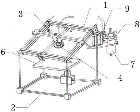
[0035] Such as figure 1As shown, a 3D printing bone platform includes an upper bracket 1 and a lower bracket 2 that are flexibly connected. The upper bracket 1 is square, and the bottom surface of the lower bracket 2 is square. The lower bracket 2 includes four vertical support rods. The vertex of 1 is connected to the vertex of the bottom surface of the lower support 2 through the support rod, and the support rod is movably connected with the upper support 1. The upper support 1 can be turned over with the connection point as the midpoint. The upper support 1 is provided with a print head 4, and the upper support 2 A melt-out device is fixedly installed, and the melt-out device is connected with the print head 4 through a sampling tube. The melting device includes a sample reservoir 8, the lower surface of the sample reservoir 8 is provided with a heating device 7, the sample reservoir 8 is connected to the nozzle through a vacuum pump 9, and the nozzle is connected to the pr...

Embodiment 2

[0040] Nano-hydroxy calcium phosphate / polycaprolactone / polylactic acid is prepared by the following method: through the reaction formula Ca(NO 3 )·4H 2 O+(NH 4 ) 2 HPO 4 → Ca 10 (PO 4 ) 6 (OH) 2 To prepare nano-hydroxycalcium phosphate, configure nano-calcium hydroxyphosphate into a slurry with a mass fraction of 5%, add the slurry to a three-necked bottle with a water separator, a stirring device and a condensation device, and add 150mL solvent DMAC and an appropriate amount of polyethylene glycol at the same time. For diol, the temperature is gradually increased to 100°C, dehydrated at 100-120°C, then polycaprolactone and polylactic acid are added in proportion, stirred and compounded for 4 hours at 120-130°C, taken out, and washed with hot deionized water for 4 hours times, washed with ethanol twice, and dried at 50-60°C for 48 hours to obtain a composite material.


PUM

PropertyMeasurementUnit
thicknessaaaaaaaaaa
porosityaaaaaaaaaa
quality scoreaaaaaaaaaa

Abstract

The invention discloses a 3D printing bone platform and belongs to the field of 3D printing. The 3D printing bone platform comprises an upper bracket and a lower bracket which are movably connected with each other, wherein the upper bracket is of square shape; the bottom of the lower bracket is of square shape; the lower bracket comprises four support rods along the vertical direction; the vertex of the upper bracket is connected with the vertex of the bottom of the lower bracket through the support rods; the support rods are moveably connected with the upper bracket; the upper bracket can be overturned around the joint point; a print head is arranged on the upper bracket; a fusing device is fixedly arranged above the lower bracket; the fusing device is connected with the print head through a sampling pipe. The 3D printing bone platform provided by the invention has excellent biocompatibility and can supply growth cavity to the tissue cells; the print bone transplanted into the biological body can survive and be integrally fused with the transplant receptor; the printing precision is ultrahigh; the platform can correct at any time and accurately control the flow, so that the artificial bone completely matched with the original bone system can be acquired.

Description

technical field [0001] The invention relates to a printing platform, in particular to a 3D printing bone platform. Background technique [0002] Traditional bone repair or replacement methods include autologous bone grafting, allogeneic bone grafting, and bone lengthening, but these processes are time-consuming. With the development of science and technology, emerging bone tissue engineering scaffolds can replace traditional bone damage repair and replacement methods, and quickly perform bone repair. The preparation of existing bone tissue engineering scaffolds usually adopts solution casting / ion elution method, in situ forming method, electrospinning method, phase separation / lyophilization method, gas pore forming method, etc. These preparation methods have obtained comparative results. Satisfactory results, but unsatisfactory in terms of accuracy, pore uniformity, spatial structure complexity, and bracket customization. Although 3D printing of bones is possible with exis...

Claims


Application Information

Patent Timeline
Patent Type & Authority Applications(China)
IPC IPC(8): A61L27/18A61L27/38A61L27/12A61L27/56A61L27/58B33Y30/00
CPCA61L27/18A61L27/12A61L27/3834A61L27/56A61L27/58A61L2430/02A61L2430/40B33Y30/00
Inventor 郑浩
Owner 成都测迪森生物科技有限公司
Why Eureka
Try Eureka