Face-fired boiler advanced denitration burning method

A combustion method and boiler technology, applied in the direction of combustion method, use of multiple fuels, combustion types, etc., can solve problems such as limited scope of application, ammonia escape, high requirements for boiler working conditions, etc., to achieve wide applicability and reduce emissions Value, the effect of reducing the cost of denitrification

Active Publication Date: 2016-12-21
DONGFANG BOILER GROUP OF DONGFANG ELECTRIC CORP +1
View PDF5 Cites 16 Cited by
  • Summary
  • Abstract
  • Description
  • Claims
  • Application Information

AI Technical Summary

Problems solved by technology

And because it is arranged after the exhaust air, if too much ammonia is injected, it will also cause ammonia to escape, so the requirements for the working conditions of the boiler are relatively high, and the scope of application is limited

Method used


Image

  • Face-fired boiler advanced denitration burning method
  • Face-fired boiler advanced denitration burning method
  • Face-fired boiler advanced denitration burning method

Examples


Embodiment 1

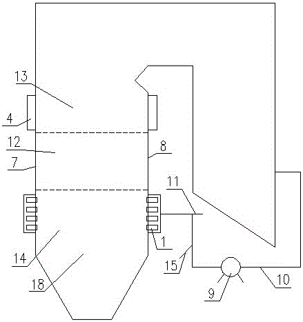
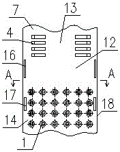
[0043] Such as figure 1 , figure 2 , image 3 , Figure 4 As shown, the hedging boiler has several layers of burn-off air nozzles 4 on the upper part of the front wall 7 and rear wall 8 of the furnace, and several layers of swirl burners on each layer of the lower part of the front wall 7 and rear wall 8 of the furnace. 1. The swirl burner 1 is provided with a primary air nozzle 2 and a secondary air nozzle 3, and the center line of the swirl burner 1 close to the two side walls 18 of each layer is offset from the center of the furnace by 5° to 45°; the furnace is from From bottom to top, it is divided into the main combustion zone 14 corresponding to the swirl burner 1, the reduction zone 12 between the overburning air nozzle 4 and the swirl burner 1, and the burnout zone 13 corresponding to the overburning air nozzle 4. The front and rear walls of the reduction zone 12 and the main combustion zone 14 are provided with purge air nozzles 16 and 17 on both sides of the fron...

Embodiment 2

[0047] Such as Figure 5 , Figure 6 As shown, the difference between the present embodiment and the first embodiment is that an independent reduction inhibitor nozzle 19 is set in the primary air nozzle 2 of several swirl burners 1, and the end of the reduction inhibitor nozzle 19 is located at the primary air nozzle 2 Outside the end of the exhaust, the reduction inhibitor nozzle 19 is connected to the tail flue before the air preheater through the pipeline 10 and the fan 9, and the mixing pipe 15 is connected to the pipeline 10; during combustion, the tail smoke from the boiler air preheater The channel extracts part of the flue gas through the blower 9 as the transport medium of the amino reduction inhibitor, mixes it with the amino reduction inhibitor mixed through the dosing pipe 15, and sprays it into the furnace from the reduction inhibitor nozzle 19; this embodiment is more conducive to the realization of the furnace The reducing atmosphere and the temperature of the...

Embodiment 3

[0049] Such as Figure 7 , Figure 8 As shown, the difference between the present embodiment and the second embodiment is only that several reduction inhibitor spouts 20 are relocated to the four corners of the hearth between the two-layer swirl burners 1 and on the front wall 7 and the rear wall 8; , the amino reduction inhibitor is injected into the amino reduction inhibitor through several reduction inhibitor spouts 20, and the amino reduction inhibitor of the same layer is sprayed in the manner of forming two imaginary tangential circles in the furnace; wherein the reduction inhibitor spout 20 aperture is 1~ 10mm, the opening is fan-shaped, the opening angle is between 10° and 150°, the injection speed of the amino reduction inhibitor is between 10m / s and 400m / s, and the diameter of the tangential circle can be adjusted by adjusting the deflection angle of the reduction inhibitor nozzle 20 The size and direction of rotation meet the needs of different working conditions; ...


PUM


Abstract

The invention discloses a face-fired boiler advanced denitration burning method. The method comprises the following steps: fire coal is sent to a hearth through primary air in the primary air nozzles of a plurality of turbulent burners in each of layers of turbulent burners arranged on a front wall and a rear wall and is burnt, secondary air is introduced through secondary air nozzles of the turbulent burners, over fire air is introduced through one or more layers of over fire air nozzles on the front wall and the rear wall, the primary air and the secondary air on the front wall and the rear wall are oppositely introduced, the excess air coefficient range of the main burning area of the turbulent burners is 0.5-1.05, and the fire coal undergoes low oxygen burning; the excess air coefficient range of the over fire area of the over fire air nozzles is 1.05-1.3, and oxygen rich burning is carried out; and one or more layers of an amino reduction inhibitor are injected to the hearth under the uppermost over fire layer to reduce nitrogen oxides in flue gas in high temperature environment in the hearth and inhibit generation of new nitrogen oxides. The face-fired boiler advanced denitration burning method has the advantages of substantial reduction of the nitrogen oxide discharge value of the outlet of the hearth, realization of ultralow discharge, no strict temperature window or catalyst, great reduction of the denitration cost, and prevention of high temperature corrosion of water screens in the boiler.

Description

technical field [0001] The invention relates to a denitrification combustion method used in an opposing boiler. Background technique [0002] During the combustion of coal, nitrogen oxides (NOx) pollutants will be emitted. These pollutants will cause photochemical smog pollution, which will cause serious harm to the human respiratory system and the survival of animals and plants. my country's latest "Emission Standards of Air Pollutants for Thermal Power Plants" (GB 13223-2011) stipulates that since January 1, 2015, all coal-fired boiler nitrogen oxides (in NO 2 meter) The emission limit is 100mg / Nm 3 (Where a W-shaped flame furnace is used, the limit for existing circulating fluidized bed thermal power boilers and thermal power boilers completed and put into operation before December 31, 2003 is 200 mg / Nm 3 ). [0003] Compared with the four-corner tangential boiler using the direct-flow pulverized coal burner, the hedging boiler using the swirl pulverized coal burner ha...

Claims


Application Information

Patent Timeline
Patent Type & Authority Applications(China)
IPC IPC(8): F23C5/28
CPCF23C5/28Y02E20/34
Inventor 陈灿王勇范卫东胡修奎周棋刘泰生但家瑜李旭升刘亚成
Owner DONGFANG BOILER GROUP OF DONGFANG ELECTRIC CORP
Why Eureka
Try Eureka