
Silicon-based TEM wave antenna array based on MEMS technology and manufacturing method of antenna array

A technology of antenna array and manufacturing method, which is applied in the direction of antenna array, antenna, electrical components, etc., can solve the problems of difficult heat dissipation, high power density, and limited application, and achieve the effect of stable pattern and wide bandwidth

Active Publication Date: 2017-02-01
THE 13TH RES INST OF CHINA ELECTRONICS TECH GRP CORP +1
View PDF12 Cites 2 Cited by
  • Summary
  • Abstract
  • Description
  • Claims
  • Application Information

AI Technical Summary

Problems solved by technology

The surface micromachining process is to deposit a sacrificial layer and a structural layer on the surface of a silicon wafer, and then etch away the sacrificial layer to obtain the required microstructure. This process is very complicated and the final structure produced is generally a planar structure.
[0005] The LIGA process is also a kind of MEMS micromachining process. Based on X-ray lithography technology, the process includes X-ray deep synchrotron radiation lithography, electroforming and plastic casting. The microstructure produced by LIGA has an aspect ratio of up to More than 200 and can make arbitrarily complex graphic structures; but X-ray lithography requires synchrotron radiation light source, the cost is high, and it is difficult to integrate with IC
LTCC is the mainstream technology for the integration of multilayer structures today. LTCC technology is to make the required circuit pattern on the green ceramic tape made of low-temperature sintered ceramic powder, and then laminate and sinter at 900 ° C to form a three-dimensional space. High-density circuits that do not interfere with each other; but LTCC has many shortcomings: the mismatch between the sintering characteristics of the substrate and the slurry during co-firing will lead to uneven surface of the fired substrate, and the large number of layers and high power density make heat dissipation a problem. The accuracy of the antenna made by the LTCC process is limited, which limits the application of the LTCC process in millimeter wave antennas
[0006] The SU-8 photoresist process uses the low absorption rate of SU-8 glue in the near-ultraviolet range to produce a microstructure with a high aspect ratio, the aspect ratio can reach 50:1 and the sidewall is almost vertical, but SU- 8 Photoresist technology cannot guarantee the accuracy of lateral dimensions
Diffusion welding is a process that uses the principle of atomic diffusion to form a reliable connection between two layers of metals. However, this process has strict requirements on the surface finish and flatness of the two surfaces that are bonded to each other. It takes a long time for diffusion and requires a one-time investment in equipment. Large, high cost, not suitable for continuous mass production
SIW is a planar rectangular metal waveguide, which is often used to make millimeter-wave slot arrays and patch arrays, but the dielectric loss in the millimeter-wave band is large and the large number of metal vias required by SIW complicate production

Method used


Image

  • Silicon-based TEM wave antenna array based on MEMS technology and manufacturing method of antenna array
  • Silicon-based TEM wave antenna array based on MEMS technology and manufacturing method of antenna array
  • Silicon-based TEM wave antenna array based on MEMS technology and manufacturing method of antenna array

Examples


Embodiment Construction

[0037] The technical solutions in the embodiments of the present invention are clearly and completely described below in conjunction with the accompanying drawings in the embodiments of the present invention. Obviously, the described embodiments are only part of the embodiments of the present invention, not all of them. Based on the embodiments of the present invention, all other embodiments obtained by persons of ordinary skill in the art without making creative efforts belong to the protection scope of the present invention.

[0038] In the following description, a lot of specific details are set forth in order to fully understand the present invention, but the present invention can also be implemented in other ways different from those described here, and those skilled in the art can do it without departing from the meaning of the present invention. By analogy, the present invention is therefore not limited to the specific examples disclosed below.

[0039] principle: figu...


PUM


Abstract

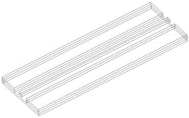
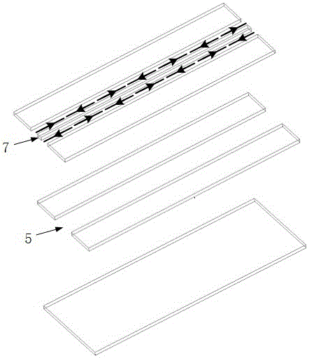
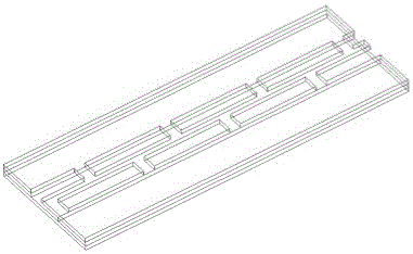
The invention discloses a silicon-based TEM wave antenna array based on an MEMS technology and a manufacturing method of the antenna array, and relates to the technical field of waveguide antennas. The antenna array comprises an antenna layer, a window layer and a coupling energy layer which are arranged from top to bottom successively and connected fixedly; the antenna layer, the window layer and the coupling energy layer are prepared by silicon-based dielectric substrates; the upper surface of the antenna layer is provided with more than two rows of rectangular etching areas, the rectangular etching areas in the same row are arranged separately, and the sizes of the rectangular etching areas are the same; and the antenna layer, the window layer and the coupling energy layer are provided with metal layers in positions except the side surfaces. On the basis of penetrated etching and surface gilding technologies in the MEMS micromachining technology, a double-conductor TEM wave transmission line whose two ends are shorted is combined with a regular magnetic flow control manner are used in the three silicon-based dielectric substrates to obtain the high-gain antenna array with stable directional diagrams in the broadband.

Description

technical field [0001] The invention relates to the technical field of waveguide antennas, in particular to a MEMS technology-based silicon-based TEM wave antenna array and a manufacturing method thereof. Background technique [0002] With people's pursuit of high-speed and high-quality wireless communication services, the Mbps-level transmission rate in the current wireless transmission technology can no longer meet the needs of current wireless communication. In addition, the existing wireless spectrum resources are becoming more and more crowded. Practitioners are urged to Develop higher frequency communication bands. The license-free 60 GHz millimeter wave frequency band has attracted more and more attention due to its abundant bandwidth resources and Gbps-level transmission rate, as well as many advantages such as frequency reuse, strong anti-interference, and easy miniaturization. The problem brought about by the increase of communication frequency to the millimeter w...

Claims


Application Information

Patent Timeline
IPC IPC(8): H01Q1/36H01Q1/38H01Q21/00
CPCH01Q1/36H01Q1/38H01Q21/00Y02D30/70
Inventor 常乐张志军王绍东高艳红
Owner THE 13TH RES INST OF CHINA ELECTRONICS TECH GRP CORP
Learn More