
Heating stage and heating stage device for X-ray microprobes and experimental method of heating stage device

A technology of microprobe and hot stage, which is applied in measuring devices, material analysis using wave/particle radiation, instruments, etc. It can solve the problems of hindering sample backscattered fluorescence detection, difficult sample centering, low X-ray transmittance, etc. problems, to achieve the effect of improving the temperature uniformity of the sample and heating the parts comprehensively

Active Publication Date: 2017-03-08
SHANGHAI INST OF APPLIED PHYSICS - CHINESE ACAD OF SCI
View PDF5 Cites 25 Cited by
  • Summary
  • Abstract
  • Description
  • Claims
  • Application Information

AI Technical Summary

Problems solved by technology

The low transmittance of the window mainly affects the detection of low atomic number elements
The window with the highest light transmittance of the Linkam hot stage is made of quartz with a thickness of 0.17mm. For X-rays with energy lower than 5keV, the light transmittance is almost zero; for 6.40keV Fe KL3 lines, the fluorescence transmittance is less than 5%. It is even more difficult to detect many important elements such as Mn, Cr, V, Ti, Sc, Ca and K with atomic numbers lower than Fe
[0006] (2) It is difficult to center the sample
This is very inconvenient to adjust the rotation center through the electric table
In addition, the high-temperature hot stage does not consider the problem of how to locate the sample when the signal characteristics of the transmission are not obvious, such as using the rotation center of the sample chamber to assist the positioning problem
[0009] (3) Sample temperature gradient and uniformity
[0011] (4) Backscattered fluorescence detection problem
Apparently, the drawbacks of low X-ray transmittance of existing commercial microscope hot stages described in problem (1) also hinder the detection of backscattered fluorescence of samples in it

Method used


Image

  • Heating stage and heating stage device for X-ray microprobes and experimental method of heating stage device
  • Heating stage and heating stage device for X-ray microprobes and experimental method of heating stage device
  • Heating stage and heating stage device for X-ray microprobes and experimental method of heating stage device

Examples


Embodiment Construction

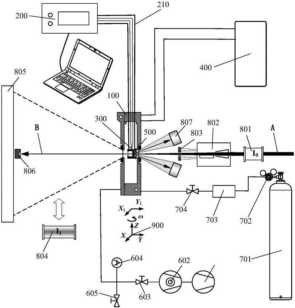
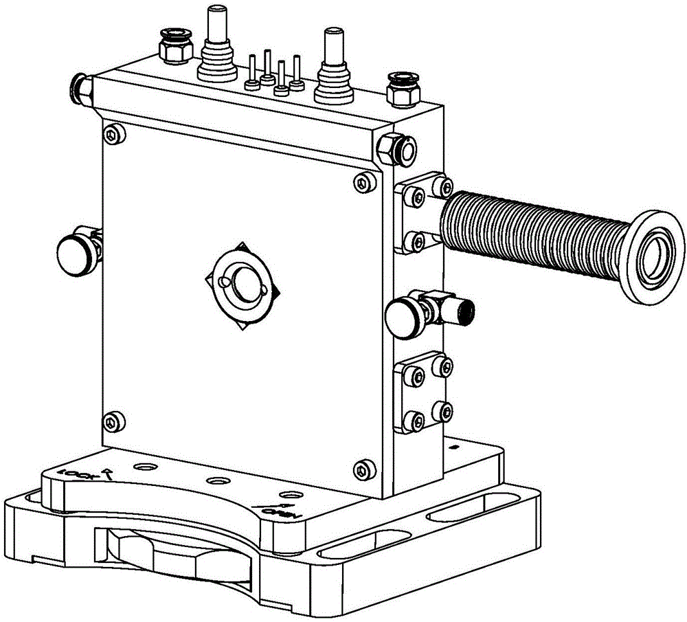
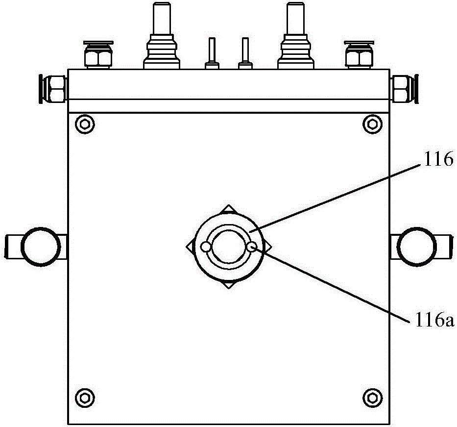
[0206] The heat stage, heat stage device and experimental method of the radiation microprobe according to the present invention will be further described in detail in conjunction with the accompanying drawings and specific embodiments below.

[0207] figure 1 The structure of the heat stage device of the radiation microprobe according to one embodiment of the present invention is shown.

[0208] Such as figure 1 shown, combined with reference figure 2 , the hot stage 100 of the hard X-ray microprobe is set on the motorized six-dimensional (X, Y, Z, ω, X 1 , Y 1 ) on the sample positioning platform 900, which are respectively connected with the temperature controller 200, the circulating water cooler 400, the vacuum pump unit (including the rotary vane vacuum pump 601, the turbomolecular pump 602) and the process / protection gas supply device. Wherein, the process / protection gas supply device includes a gas cylinder 701, a pressure reducing valve 702, a flow meter 703, and ...


PUM

PropertyMeasurementUnit
diameteraaaaaaaaaa
diameteraaaaaaaaaa
lengthaaaaaaaaaa

Abstract

The invention discloses a heating stage for X-ray microprobes. The heating stage comprises a heating stage body, a heater and a sample holder; an incident window and a transmitting window are coaxially and correspondingly arranged on the front wall and the rear wall of the heating stage body respectively, and the bottom of the heating stage body can be mounted on a sample positioning platform; the sample holder is sleeved in the heater in high heating area ratio; each of the heater and the sample holder is provided with a light transmission hole, and the light transmission hole is coaxial with the incident window and the transmitting window. The heating stage for the X-ray microprobes can be operated vertically, and temperature gradient of samples is small; in addition, the heating stage has the advantages of high light transmission, vacuum chamber, easiness in alignment, good temperature uniform of the samples, wide sample type and shape adaptability, high operation temperature limit and the like. In addition, the invention further discloses a heating stage device and an experimental method thereof. The heating stage device is high in back-scattered fluorescent detection efficiency, sufficient rotatable angle and detection angle, overall atmosphere protection and vacuum environment are provided for the samples. The heating stage, the heating stage device and the experimental method are especially suitable for hard X-ray microprobes.

Description

technical field [0001] The invention relates to an in-situ high-temperature characterization technique, in particular to a heat stage of a ray microprobe, a heat stage device and an experimental method thereof. Background technique [0002] For a long time, material research has usually been carried out using traditional scientific intuition, "cooking and screening" or "trial and error" methods, that is, based on a large amount of experimental data, repeatedly adjusting and testing the composition-process-structure-performance until a satisfactory material is obtained . This method has considerable blindness, time-consuming and labor-intensive, high cost, and low efficiency, and has increasingly become the bottleneck of social development and technological progress. The Materials Genome Project, which has emerged in recent years, intends to comprehensively increase the speed of advanced materials from discovery to application and reduce costs by integrating three major tech...

Claims


Application Information

Patent Timeline
Patent Type & Authority Applications(China)
IPC IPC(8): G01N23/00
CPCG01N23/00
Inventor 何上明李爱国闫帅高兴宇
Owner SHANGHAI INST OF APPLIED PHYSICS - CHINESE ACAD OF SCI
Learn More