Method and system for sludge pyrolysis plasma gasifying generation

A plasma and pyrolysis gas technology, applied in gasification process, pyrolysis treatment of sludge, spiral gasifier, etc., can solve problems such as shortage of human resources, achieve low cost, high yield, and no pipeline blockage Effect

Pending Publication Date: 2017-05-10
SHENWU TECH GRP CO LTD
View PDF0 Cites 3 Cited by
  • Summary
  • Abstract
  • Description
  • Claims
  • Application Information

AI Technical Summary

Problems solved by technology

[0008] The purpose of the present invention is to provide a method and system for generating electricity by sludge pyrolysis and plasma gasification, so as to simultaneously solve the defects of sludge treatment technology and the shortage of human resources

Method used


Image

  • Method and system for sludge pyrolysis plasma gasifying generation
  • Method and system for sludge pyrolysis plasma gasifying generation
  • Method and system for sludge pyrolysis plasma gasifying generation

Examples


Embodiment 1

[0063] The above-mentioned sludge pyrolysis plasma gasification power generation system was used to treat the sludge of a certain urban sewage treatment plant. The industrial analysis and elemental analysis are shown in Table 1.

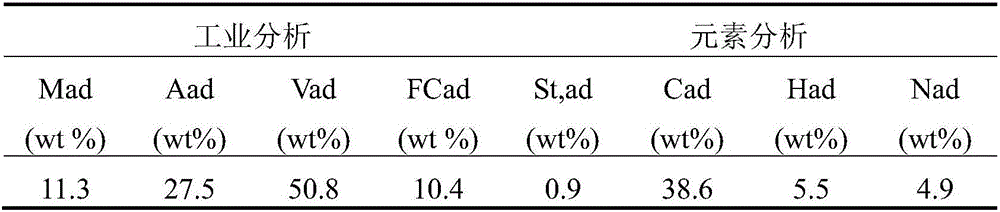
[0064] Table 1 Industrial analysis and elemental analysis of sludge

[0065]

[0066] M in this article ad Represents air-dry basis moisture; A ad Represents dry basis ash; V ad Represents volatile matter on an air-dry basis; F Cad Represents carbon content; S t,ad Represents total sulfur; C ad stands for carbon content; H ad represents the hydrogen content; N ad represents the nitrogen content.

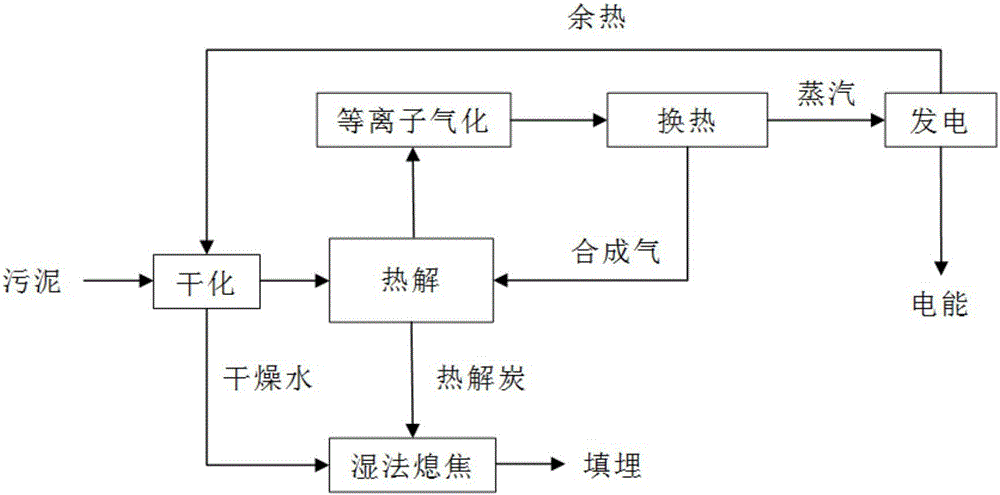
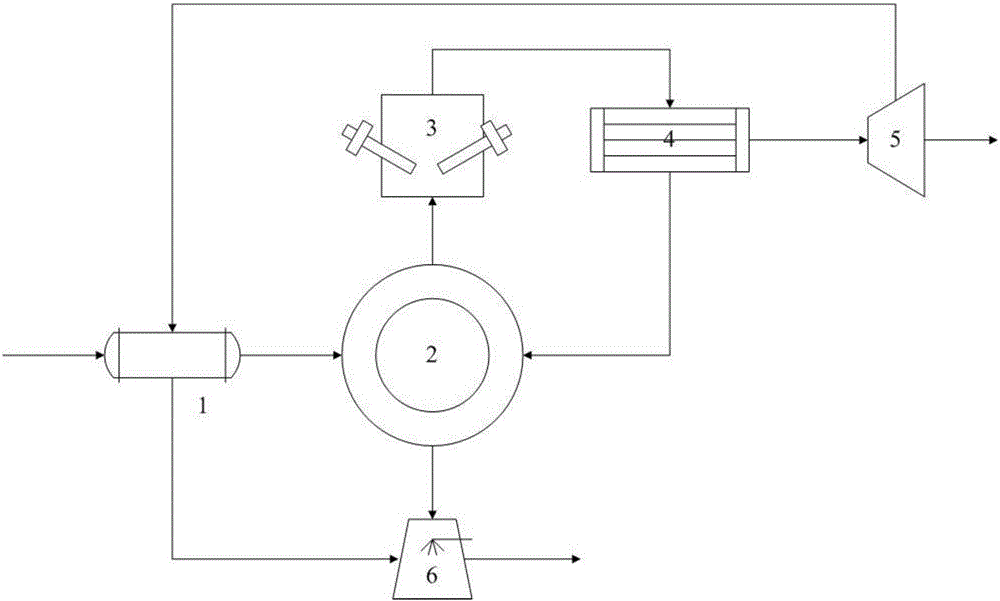
[0067] The specific treatment process is as follows: the moisture content of the sludge is 85%, and the sludge is sent to a drying device to obtain about 40% dry water. The dried sludge with moisture content reduced to 45% is sent to the regenerative rotary bed, and the temperature of the regenerative radiant tube in the pyrolysis zone is 700°C. ...

Embodiment 2

[0070] Using the sludge pyrolysis plasma gasification power generation system to treat the sludge of a certain urban sewage treatment plant, its industrial analysis and elemental analysis are shown in Table 2, and the specific treatment process is as follows:

[0071] Table 2 Industrial analysis and elemental analysis of sludge

[0072]

[0073] The moisture content of the sludge is 91%, and the sludge is sent to a drying device to obtain about 45% dry water. The dried sludge with moisture content reduced to 46% is sent to the regenerative rotating bed, and the temperature of the regenerative radiant tube in the pyrolysis zone is 800°C. After the sludge is pyrolyzed in the rotating bed, the final pyrolysis gas-liquid mixture is discharged from the top of the end of the regenerative rotating bed pyrolysis zone and enters the plasma gasification reaction chamber. The device is discharged, wherein the temperature of the plasma gasification reaction chamber is 1500°C. After t...

Embodiment 3

[0076] Using the sludge pyrolysis plasma gasification power generation system to treat the sludge of a certain urban sewage treatment plant, its industrial analysis and elemental analysis are shown in Table 3, and the specific treatment process is as follows:

[0077] Table 3 Industrial analysis and elemental analysis of sludge

[0078]

[0079] The moisture content of the sludge is 91%, and the sludge is sent to a drying device to obtain about 45% dry water. The dried sludge with moisture content reduced to 46% is sent to the regenerative rotary bed, and the temperature of the regenerative radiant tube in the pyrolysis zone is 500°C. After the sludge is pyrolyzed in the rotating bed, the final pyrolysis gas-liquid mixture is discharged from the top of the end of the regenerative rotating bed pyrolysis zone and enters the plasma gasification reaction chamber. The device is discharged, wherein the temperature of the plasma gasification reaction chamber is 1100°C. After the...


PUM


Abstract

The invention relates to a method and a system for sludge pyrolysis plasma gasifying generation. The method for sludge pyrolysis plasma gasifying generation comprises the following steps: feeding sludge into a heat accumulating type rotary bed and performing pyrolysis treatment, thereby acquiring a pyrolytic gas liquid mixture and pyrolytic gas carbon; introducing the pyrolytic gas liquid mixture into a plasma gasification reaction chamber, thereby acquiring a synthesis gas; introducing the synthesis gas into a heat exchange device for performing heat exchange treatment, thereby acquiring steam and residual synthesis gas; and introducing the steam into a generation device. The system for sludge pyrolysis plasma gasifying generation comprises the heat accumulating type rotary bed, the plasma gasification reaction chamber, the heat exchange device, the generation device and a quenching device. According to the technical scheme provided by the invention, the clean and efficient method and system for sludge pyrolysis plasma gasifying are provided; the steam acquired from the synthesis gas through heat exchange treatment is utilized to generate electricity, so that the harmless, treatment, reduction and recycling of the sludge are realized; the running cost is low; the tar yield is ultralow; the pipeline is prevented from being blocked; and the industrialization and large-scale production can be easily realized.

Description

technical field [0001] The present invention generally relates to a sludge pyrolysis technology, in particular to a sludge pyrolysis plasma gasification power generation method and system. Background technique [0002] With the improvement of environmental protection level. The amount of urban sewage treatment has been increasing year after year. As a by-product of urban sewage treatment, the annual output of urban sludge has also increased sharply, and sludge is a flocculent mud particle with a high water content (80%-95%). Aggregates formed by suspended solids and microorganisms in sewage. Sludge contains a large amount of heavy metals, nitrogen and phosphorus, pathogenic bacteria, viruses and toxic organic substances. If it is discharged into the water body randomly, it will cause the deterioration of the water body and affect the survival of aquatic organisms. If used in agriculture, it will pollute the soil, cause crop diseases, and even endanger human health. Therefo...

Claims


Application Information

Patent Timeline
Patent Type & Authority Applications(China)
IPC IPC(8): C02F11/10C10J3/00C10B39/04
CPCY02W10/40C02F11/10C10B39/04C10J3/007C10J2300/0923
Inventor 刘璐张安强任浩华蔡先明赵月晶肖磊吴道洪
Owner SHENWU TECH GRP CO LTD
Why Eureka
Try Eureka