Surface heat treatment modification method of fluorescent powder and COB light source made of fluorescent powder

A technology of surface heat treatment and modification method, which is applied in the field of LED inorganic luminescent materials, can solve the problems of increasing the production of luminescent materials and environmental protection costs, affecting the optical properties of luminescent materials, and environmentally harmful substances, so as to expand the scope of use, low cost, The effect of increasing stability

Active Publication Date: 2017-05-31
BEIJING YUJI SCI & TECH +2
View PDF3 Cites 5 Cited by
  • Summary
  • Abstract
  • Description
  • Claims
  • Application Information

AI Technical Summary

Problems solved by technology

Nitride luminescent materials are currently the most important of the few red phosphors, which have the advantages of high quantum yield and no pollutant release in the production process; There is the possibility of slow decomposition or oxidation, which restricts its application in LED packaging in areas such as high stability and special environments, especially in high-power and high-color rendering COBs with high heat generation and concentration
[0003] At present, the surface modification of nitride luminescent material pow

Method used


Image

  • Surface heat treatment modification method of fluorescent powder and COB light source made of fluorescent powder
  • Surface heat treatment modification method of fluorescent powder and COB light source made of fluorescent powder
  • Surface heat treatment modification method of fluorescent powder and COB light source made of fluorescent powder

Examples


Embodiment 1

[0060] Example 1 (Ca 0.08 Sr 0.90 )(Al 0.5 Si 0.5 ) 2 N 3 : Eu 0.02

[0061] The raw material that synthesis embodiment 1 material adopts is Sr 3 N 2 , Ca 3 N 2 , Si 3 N 4 , AlN, Eu 2 o 3 . Weigh 100 g of the raw materials shown below and mix them.

[0062]

[0063]

[0064] After weighing the above raw materials, put the powder in a mortar and mix evenly in a glove box (oxygen content<1ppm, water content<1ppm).

[0065] The mortar is onyx or alumina ceramic. Put the mixed powder into the crucible, compact it lightly, then take it out from the glove box and place it in a high-temperature graphite furnace. The material of the crucible is molybdenum or boron nitride. After the graphite furnace is evacuated and filled with nitrogen, it starts to heat up. The temperature rise rate is 10°C / min, and the nitrogen pressure is 0.8MPa. Heat up to 1800°C and keep warm for 6 hours. After the keep warm, turn off the power and cool down with the furnace. The burnt ...

Embodiment 2

[0068] Example 2 (Ca 0.08 Sr 0.90 )(Al 0.5 Si 0.5 ) 2 N 3 : Eu 0.02

[0069] The raw material that synthetic embodiment 2 material adopts is Sr 3 N 2 , Ca 3 N 2 , Si 3 N 4 , AlN, Eu 2 o 3 , Weigh 100 g of the raw materials shown below and mix them.

[0070]

[0071] After weighing the above raw materials, put the powder in a mortar and mix evenly in a glove box (oxygen content<1ppm, water content<1ppm).

[0072] Consistent with the method of preparing the finished product in Example 1, only the heat treatment surface treatment is not carried out after the finished product is produced.

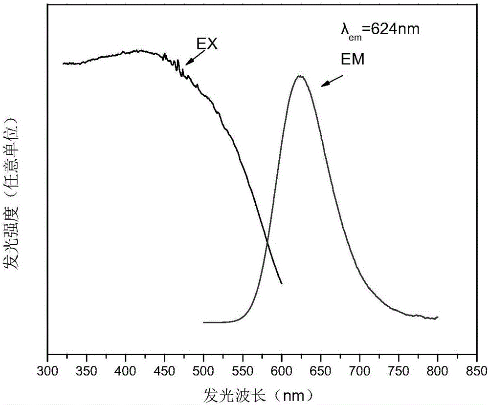
[0073] Figure 5 Be the emission spectrum of embodiment 2. Like Example 1, the excitation spectrum (EX) of Example 2 is relatively broad, indicating that the luminescent material can be excited by blue light and ultraviolet light. The emission spectrum (EM) is a broad spectrum, covering the range of 550-800nm, the half-maximum width (FWHM) is about 75nm, and the emission pe...

Embodiment 3

[0075] Example 3 (Ca 0.51 Sr 0.48 )(Al 0.5 Si 0.5 ) 2 (N 0.8 C 0.2 ) 3 : Eu 0.01

[0076] The raw material that synthetic embodiment 3 materials adopt is Sr 3 N 2 , Ca 3 N 2 , Si 3 N 4 , AlN, EuN, weigh 100g of the raw materials shown below and mix them. And using 1.0wt% porous ammonium fluoride (NH 4 F) as a flux.

[0077]

[0078] After weighing the above raw materials, put the powder in a mortar and mix evenly in a glove box (oxygen content<1ppm, water content<1ppm).

[0079] The mortar is onyx or alumina ceramic. Put the mixed powder into the crucible, compact it lightly, then take it out from the glove box and place it in a high-temperature graphite furnace. The material of the crucible is molybdenum or boron nitride. After the graphite furnace is evacuated and filled with nitrogen, it starts to heat up at a rate of 10°C / min, and the pressure of nitrogen is 1 atmosphere. Heat up to 1750°C and keep warm for 6 hours. After the keep warm, turn off the ...


PUM

PropertyMeasurementUnit
The average particle sizeaaaaaaaaaa

Abstract

The invention relates to a surface heat treatment modification method of fluorescent powder and a COB light source made of the fluorescent powder, belonging to the field of LED inorganic luminescent materials. According to the method, heating treatment is carried out on a (Ca, Q)1-y(Al, Si)2(N, T)3: Ay fluorescent powder material in an oxidative atmosphere to ensure that a compact oxide layer is formed on the surface of the fluorescent powder material; and the surface of the fluorescent powder material is modified to effectively isolate the fluorescent powder material from the external environment, so that the stability of the fluorescent powder is improved and the service life of the fluorescent powder is prolonged. According to the method, the stability of single-phase nitrides can be improved to ensure that the nitrides are beneficial for the absorption and emission of light, thereby improving the performance and stability of nitride red powder after LED packaging. When the nitride red powder prepared through the method is matched with an ultraviolet, near-ultraviolet or blue LED and other light emitting materials such as yttrium aluminum garnet and the like, the COB light source with high power and high coloration can be prepared; and after the COB light source is continuously lightened for 1000 hours, the lumen depreciation is zero.

Description

technical field [0001] The invention relates to a surface heat treatment modification method of fluorescent powder, the modified fluorescent powder and a COB light source made thereof, which belong to the field of LED inorganic luminescent materials. Background technique [0002] GaN-based light-emitting diode (Light-Emitting Diode) has the advantages of energy saving, no pollution sources such as mercury, high efficiency, low maintenance cost, long life and small size. It has gradually replaced various traditional light bulbs and fluorescent lamps, and is widely used in indoor Lighting, signal lamps, indicator lights, vehicle lights, display screens, advertising screens, outdoor large-scale screens and other light-emitting devices are known as new green energy and new light-emitting devices that are energy-saving and environmentally friendly in the field of solid-state lighting in the 21st century. In order to obtain higher color rendering index and white light with differe...

Claims


Application Information

Patent Timeline
IPC IPC(8): C09K11/02C09K11/64C09K11/65H01L33/50H01L33/26
CPCC09K11/025C09K11/0883C09K11/7728H01L33/26H01L33/502
Inventor 鲁路吴振雄张辽黄永宣刘晓东聂朦黎力贾晓卿
Owner BEIJING YUJI SCI & TECH
Why Eureka
Try Eureka