A microfluidic chip for fluorescent immunoassay and its preparation method

A technology of microfluidic chips and fluorescent immunity, applied in the field of medical testing, can solve the problems of large batches, no quality control area, intra-batch variation, etc., to improve product quality, reduce product batch and/or intra-batch variation , the effect of good detection sensitivity

Active Publication Date: 2018-02-13
TIANJIN SAVANT BIOTECH CO LTD
View PDF5 Cites 0 Cited by
  • Summary
  • Abstract
  • Description
  • Claims
  • Application Information

AI Technical Summary

Problems solved by technology

[0003] However, there is only one signal detection area on the currently disclosed microfluidic chip, and there is no quality control area.
This kind of chip manufacturing process is simple, but in practical applications, it will cause large batch-to-batch and / or intra-batch variation

Method used


Image

  • A microfluidic chip for fluorescent immunoassay and its preparation method
  • A microfluidic chip for fluorescent immunoassay and its preparation method

Examples


preparation example Construction

[0056] The preparation method of the phosphate buffer is: dissolving sodium dihydrogen phosphate and disodium hydrogen phosphate in water;

[0057] The preparation method of described citric acid-sodium citrate buffer solution is: trisodium citrate, citric acid and sodium hydroxide are dissolved in water;

[0058] The preparation method of the blocking solution is as follows: bovine serum albumin, sucrose, sodium dihydrogen phosphate, disodium hydrogen phosphate and Proclin300 are dissolved in water.

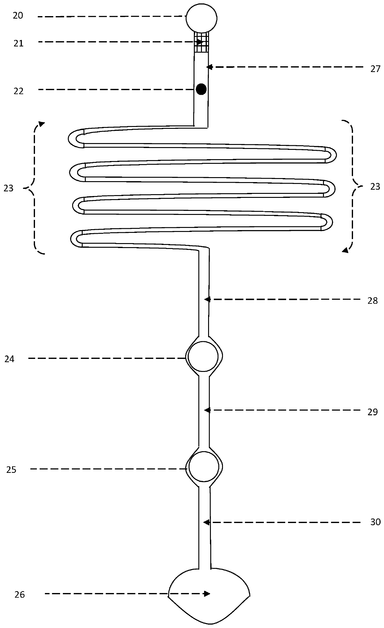
[0059] Detection principle:

[0060] As shown in the figure, driven by centrifugal force, the whole blood sample passes through the filter zone to remove blood cells, and then passes through the antibody coating zone;

[0061] Use the water in the sample to dry the biotin-labeled biotin-labeled with the analyte antibody, fluorescent microspheres labeled with the analyte antibody, fluorescent microspheres labeled quality control antibody, and then the mixture moves together to ...

Embodiment 1

[0067] In the following, the present invention will be described by taking a microfluidic chip for detecting cardiac troponin I (cTnI) as an example:

[0068] 1. Treatment of whole blood filtration area

[0069] Cut the red blood cell filter membrane into corresponding specifications, and stick it on the whole blood filter area with an instrument.

[0070] 2. Treatment of antibody-coated area

[0071] 2.1 Biotin-labeled mouse anti-cTnI monoclonal antibody

[0072] First, dilute the biotin-labeled mouse anti-cTnI monoclonal antibody to 1 mg / mL with sodium carbonate buffer, and dialyze with sodium carbonate buffer at room temperature (25°C±5°C) for 4 hours in the dark; 6-Aminocaproic acid-N-hydroxysuccinimide-biotin (BCNHS) was prepared in methylamide (DMF) to 1 mg / mL; add 125 μL of the above DMF solution to 1 mL of mouse anti-cTnI monoclonal antibody solution for biotin labeling Mix in a glass bottle, stir at room temperature (25°C±5°C) in the dark for 2 hours; add 9.6 μL of...

Embodiment 2

[0133] The microfluidic chip for detecting cardiac troponin I (cTnI) in this example is similar to that in Example 1, the only difference is the biotin-labeled analyte antibody in the antibody-coated area and the analyte labeled with fluorescent microspheres The molar ratio of antibody and fluorescent microsphere-labeled quality control antigen = 4:1:1.

[0134] Using the microfluidic chip of the present embodiment, the detected data shows that the corresponding data of T / C and cardiac troponin I concentration are as follows:

[0135] Table II:

[0136] Cardiac troponin I concentration


PUM


Abstract

The invention discloses a microfluidic chip for fluorescence immunity detection. The microfluidic chip comprises a chip substrate, at least one microfluidic channels are formed in the chip substrate, each microfluidic channel comprises a sample dropping area, a full-blood filtering area, an antibody-coating area, a reaction area, a detection area, a quality control area and a waste liquid collecting area; an erythrocyte membrane is arranged in the full-blood filtering area; the antibody-coating area is coated with a biotin labeled antibody to be detected, a fluorescent microsphere labeled antibody to be detected and a fluorescent microsphere labeled quality control antigen; streptavidin coated polystyrene microspheres are arranged in the detection area; antibody coated polystyrene microspheres of the quality control antigen are arranged in the quality control area.

Description

technical field [0001] The invention belongs to the field of medical testing, and in particular relates to a microfluidic chip for fluorescent immunodetection and a preparation method thereof. Background technique [0002] In recent years, the field of bioanalysis technology has developed rapidly, and many important research directions have emerged. Microfluidic chip analysis technology is one of the most active ones, and has received extensive attention in both scientific research and application fields. As a new type of analysis and detection platform, microfluidic chips have the advantages of high throughput, integration, portability, easy operation, and low cost, and have been widely used in many fields. [0003] However, the currently disclosed microfluidic chip has only one signal detection area and no quality control area. This kind of chip manufacturing process is simple, but it will cause large batch-to-batch and / or intra-batch variation in practical applications....

Claims


Application Information

Patent Timeline
Patent Type & Authority Patents(China)
IPC IPC(8): B01L3/00G01N33/58G01N33/544G01N33/543G01N33/533
CPCB01L3/5027B01L3/502707B01L3/502753B01L2200/10G01N33/533G01N33/54313G01N33/544G01N33/582G01N33/585
Inventor 林斯
Owner TIANJIN SAVANT BIOTECH CO LTD
Why Eureka
Try Eureka