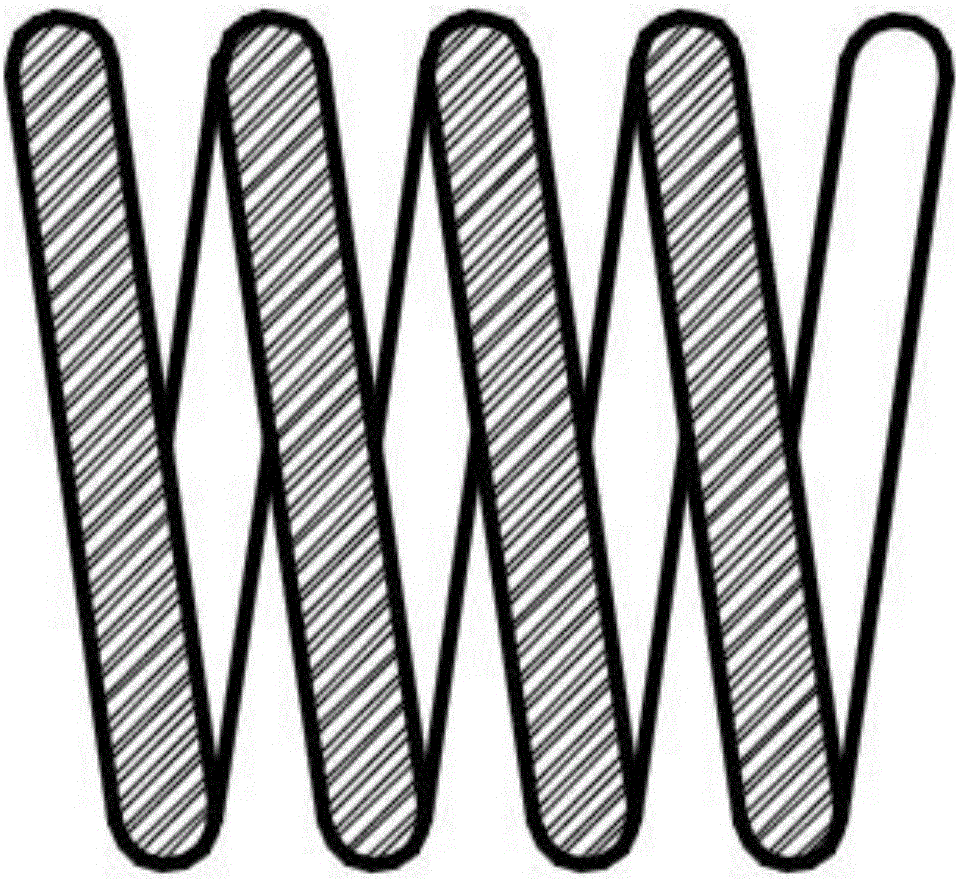
LED patch light source

A technology of LED patch and light source, which is applied in the field of LED lighting, can solve the problems of high thermal conductivity, poor plasticity, and easy to break, and achieve high thermal conductivity, reduced packaging area, and good corrosion resistance.

Inactive Publication Date: 2017-06-13
GUANGDONG REAL FAITH LIGHTING TECH
View PDF14 Cites 3 Cited by
  • Summary
  • Abstract
  • Description
  • Claims
  • Application Information

AI Technical Summary

Problems solved by technology

[0007] In order to overcome the defects of the prior art, the object of the present invention is to provide an LED patch light source, which uses a flexible and flexible PCB board, which can solve the problem of poor plasticity of the hard-based ceramic-based PCB aluminum substrate, and is prone to breakage when it is flexible and flexible. It has high thermal conductivity / heat dissipation, corrosion resistance, and excellent winding and winding performance. At the same time, the thermal conductivity of the patch light source is high, and it can be bent and folded to enhance the three-dimensional effect, forming a COB light source that emits light from all angles of 360° and does not Blue light leakage, cost saving, easy packaging, greatly prolonging the service life

Method used


Image

  • LED patch light source
  • LED patch light source
  • LED patch light source

Examples


Embodiment 1

[0057] Ceramic slurry includes the following components:

[0058] 80 parts by weight of alumina ceramic powder,

[0059] The bisphenol A type epoxy resin of 15 parts by weight,

[0060]1 part by weight of acetone,

[0061] The polyether defoamer of 1 weight part,

[0062] The KH570 coupling agent of 1 weight part,

[0063] 2 parts by weight of aniline curing agent.

[0064] S1: Ceramic powder preparation:

[0065] S11: select the particle size D50 value of 20um alumina ceramic powder, add water solvent, and ball mill the slurry obtained for 5 hours,

[0066] S12: Filter the slurry to remove water and freeze-dry for 24 hours to obtain a ceramic powder with a D50 value of 5um and a water content of less than 1%.

[0067] S2: Preparation of ceramic slurry: Weigh 80 parts by weight of alumina ceramic powder, 15 parts by weight of bisphenol A epoxy resin, 1 part by weight of acetone, 1 part by weight of polyether defoamer, 1 part by weight The KH570 coupling agent and the an...

Embodiment 2

[0084] Ceramic slurry includes the following components:

[0085] 70 parts by weight of alumina ceramic powder,

[0086] 10 parts by weight of bisphenol A type epoxy resin,

[0087] 0.8 parts by weight of ethyl acetate,

[0088] 0.8 parts by weight of silicone defoamer,

[0089] The KH560 coupling agent of 0.8 weight part,

[0090] 1.5 parts by weight of an acid anhydride curing agent.

[0091] S1: Ceramic powder preparation:

[0092] S11: select the particle size D50 value of 20um alumina ceramic powder, add water solvent, and ball mill the slurry obtained for 5 hours,

[0093] S12: Filter the slurry to remove water and freeze-dry for 24 hours to obtain a ceramic powder with a D50 value of 5um and a water content of less than 1%.

[0094] S2: Preparation of ceramic slurry: Weigh 70 parts by weight of alumina ceramic powder, 10 parts by weight of bisphenol A epoxy resin, 0.8 parts by weight of ethyl acetate, 0.8 parts by weight of organosilicon defoamer, 0.8 parts by wei...


PUM

PropertyMeasurementUnit
lengthaaaaaaaaaa
widthaaaaaaaaaa
thicknessaaaaaaaaaa

Abstract

The invention provides an LED patch light source. The LED patch light source comprises a flexible and bendable PCB (printed circuit board) which is 150-300 mm long and 3-8 mm wide, wherein the PCB board comprises an insulation layer and a heat dissipation layer; the insulation layer is formed by sintering ceramic slurry; the heat dissipation layer is a flexible aluminum foil which is 0.1-0.6 mm thick. The preparation method of the LED patch light source comprises steps as follows: (1) cleaning; (2) die bond; (3) wire welding; (4) dam surrounding; (5) uniformization of adhesive dispensing powder, and the LED patch light source is obtained. The problems that a hard-ceramic-matrix PCB aluminum substrate has poor plasticity and easily breaks during flexible bending are solved. The method for preparing the PCB substrate is simple and high in preparation efficiency. The prepared LED patch light source has stable performance and long service life.

Description

technical field [0001] The invention belongs to the technical field of LED lighting, and in particular relates to an LED patch light source. Background technique [0002] PCB board, also known as printed circuit board, is the provider of electrical connection for electronic components. Its invention greatly reduces the errors of wiring and assembly, and improves the automation level and production labor rate. [0003] Traditional PCB boards include organic composite material substrates represented by epoxy resin bases and inorganic composite material substrates represented by aluminum substrates. However, organic composite substrates represented by epoxy resin have poor thermal conductivity, brittleness and poor plasticity, which restrict the application of PCB boards in high-power complex integrated circuits, while inorganic composite materials represented by aluminum substrates The thermal conductivity of the substrate is not ideal, the plasticity is poor, the surface of...

Claims


Application Information

Patent Timeline
Patent Type & Authority Applications(China)
IPC IPC(8): F21K9/20F21V19/00F21V29/85F21Y115/10
CPCF21V19/005F21V29/86
Inventor 丁天昊董睿智丁萍
Owner GUANGDONG REAL FAITH LIGHTING TECH
Why Eureka
Try Eureka