A method for regulating the luminescence performance of fluorescent materials in a solid-state environment and an all-solid-state electronically written optical readout memory unit

A technology of fluorescent material and luminescence performance, which is applied in the field of all-solid-state electrical writing optical readout memory cells, can solve problems such as restricting applications, and achieve the effect of expanding application fields and good application prospects.

Active Publication Date: 2020-05-08
NINGBO INST OF MATERIALS TECH & ENG CHINESE ACADEMY OF SCI
View PDF8 Cites 0 Cited by
  • Summary
  • Abstract
  • Description
  • Claims
  • Application Information

AI Technical Summary

Problems solved by technology

At present, redox under the action of an electric field is often used to regulate the fluorescence properties of fluorescent materials, but this regulation needs to be realized in a liquid environment, which greatly limits its practical application.

Method used


Image

  • A method for regulating the luminescence performance of fluorescent materials in a solid-state environment and an all-solid-state electronically written optical readout memory unit
  • A method for regulating the luminescence performance of fluorescent materials in a solid-state environment and an all-solid-state electronically written optical readout memory unit
  • A method for regulating the luminescence performance of fluorescent materials in a solid-state environment and an all-solid-state electronically written optical readout memory unit

Examples


Embodiment 1

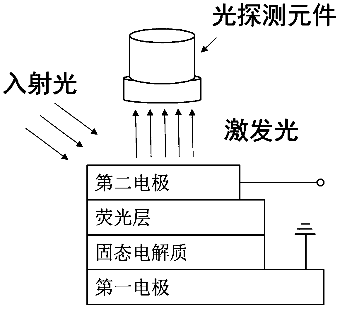
[0036] In this embodiment, the structure of the all-solid-state fluorescent material unit is as follows figure 1 As shown, it includes a first electrode on the surface of the substrate, a solid electrolyte layer on the surface of the first electrode, a fluorescent layer on the surface of the solid electrolyte layer, and a second electrode on the surface of the fluorescent layer.

[0037] The first electrode is located on the surface of the substrate material Si.

[0038] The first electrode layer consists of platinum.

[0039] The second electrode layer is composed of transparent and conductive ITO (Indium Tin Oxide).

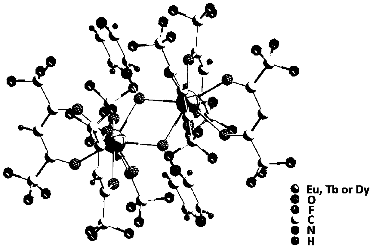
[0040] The thickness of the fluorescent material layer is 100nm, which is composed of a fluorescent compound containing rare earth europium, and its molecular formula is [Eu(hfac) 3 PraNO] 2 , where hfac refers to hexafluoroacetylacetone, PraNO refers to pyrazine nitrogen oxide, and its structure is as figure 2 shown. Among them, the non-metal atoms that ...

Embodiment 2

[0056] In this embodiment, the composition structure of the all-solid-state fluorescent material unit is basically the same as that of the all-solid-state fluorescent material unit in Example 1, except that the rare-earth europium in Example 1 is replaced by rare-earth terbium in the fluorescent compound material.

[0057] The preparation method of the fluorescent compound material is basically the same as that in Example 1, except that the rare earth europium in Example 1 is replaced by rare earth terbium.

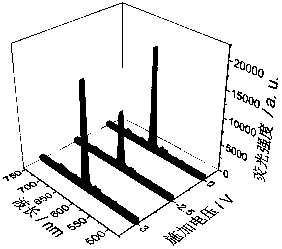
[0058] The fluorescent material layer is irradiated with incident light with a wavelength of 350nm, and the fluorescent material layer is excited to emit excitation light, and the intensity of the excitation light is detected by a fluorescence spectrum detector ANDOR (IR303). When no voltage signal is applied between the first electrode and the second electrode, such as image 3 As shown, the excitation light has the strongest light intensity at a wavelength of 545 nanome...

Embodiment 3

[0071] In this embodiment, the composition structure of the all-solid-state fluorescent material unit is basically the same as the structure of the all-solid-state fluorescent material unit in Example 1, except that the rare-earth dysprosium in the fluorescent compound material replaces the rare-earth europium in Example 1.

[0072] The preparation method of the fluorescent compound material is basically the same as that in Example 1, except that the rare earth europium in Example 1 is replaced by rare earth dysprosium.

[0073] The fluorescent material layer is irradiated with incident light with a wavelength of 350nm, and the fluorescent material layer is excited to emit excitation light, and the intensity of the excitation light is detected by a fluorescence spectrum detector ANDOR (IR303). When no voltage signal is applied between the first electrode and the second electrode, such as image 3 As shown, the excitation light has the strongest light intensity at a wavelength ...


PUM

PropertyMeasurementUnit
thicknessaaaaaaaaaa

Abstract

The invention provides a method of regulating and controlling a luminescent property of a fluorescent material in a solid-state environment. According to the method, a method that under an effect of an electric field, metal ions in an electrolyte material layer are directionally moved to a fluorescent material layer, and interact with the fluorescent material to enable a quenching effect to occur to photons to cause luminescent property changing is utilized to realize all-solid-state regulation and control. Reversible regulation and control can be realized through adjusting a voltage signal, and an all-solid-state storage mode of electrical signal writing and optical signal reading can be realized by utilizing the reversible regulation and control, can be used for high-density information storage, can also be used for interference-free and high-throughput transmission of information, greatly expands application fields of the fluorescent material, and has good application prospects.

Description

technical field [0001] The invention belongs to the technical field of fluorescent materials and storage devices, and in particular relates to a method for regulating and controlling the luminous performance of fluorescent materials in a solid-state environment and an all-solid-state electrical writing optical readout storage unit realized by the method. Background technique [0002] The development trend of massive information data and device miniaturization brought by the era of big data requires information storage devices to store information data at high density. Due to limitations in production technology and storage principles, existing commercial magnetic storage materials and information storage materials based on silicon-based semiconductor materials can no longer meet the requirements for high-density storage of massive data. Utilizing molecular materials with stimuli-responsive functions is one of the ways to achieve high-density information storage. [0003] Th...

Claims


Application Information

Patent Timeline
Patent Type & Authority Patents(China)
IPC IPC(8): G11C13/04C09K11/06
CPCC09K11/06C09K2211/1466G11C13/04
Inventor 伊晓辉刘钢李润伟
Owner NINGBO INST OF MATERIALS TECH & ENG CHINESE ACADEMY OF SCI
Why Eureka
Try Eureka