Two-stage low temperature gasification device based on low-order fuel autocatalysis, and two-stage low temperature gasification method based on low-order fuel autocatalysis

A low-temperature gasification and fuel technology, which is applied in the direction of granular/powder fuel gasification, gasification process, and production of combustible gas, can solve the problems of catalyst content reduction, tar content increase, unfavorable tar retention, etc., and achieve easy scale-up , low tar content, and the effect of flexible raw material handling capacity

Active Publication Date: 2017-12-22
哈尔滨丰瀛投资有限公司
View PDF13 Cites 6 Cited by
  • Summary
  • Abstract
  • Description
  • Claims
  • Application Information

AI Technical Summary

Problems solved by technology

However, there is a carrier gas passing through the pyrolysis fuel bed, which is not conducive to the in-situ catalytic decomposition of tar and the retention of alkali metals and alkaline earth metals in the coke, so that the tar content in the pyrolysis gas entering the gasifier increases, and the pyrolysis The content of catalyst i

Method used


Image

  • Two-stage low temperature gasification device based on low-order fuel autocatalysis, and two-stage low temperature gasification method based on low-order fuel autocatalysis
  • Two-stage low temperature gasification device based on low-order fuel autocatalysis, and two-stage low temperature gasification method based on low-order fuel autocatalysis
  • Two-stage low temperature gasification device based on low-order fuel autocatalysis, and two-stage low temperature gasification method based on low-order fuel autocatalysis

Examples


specific Embodiment approach 1

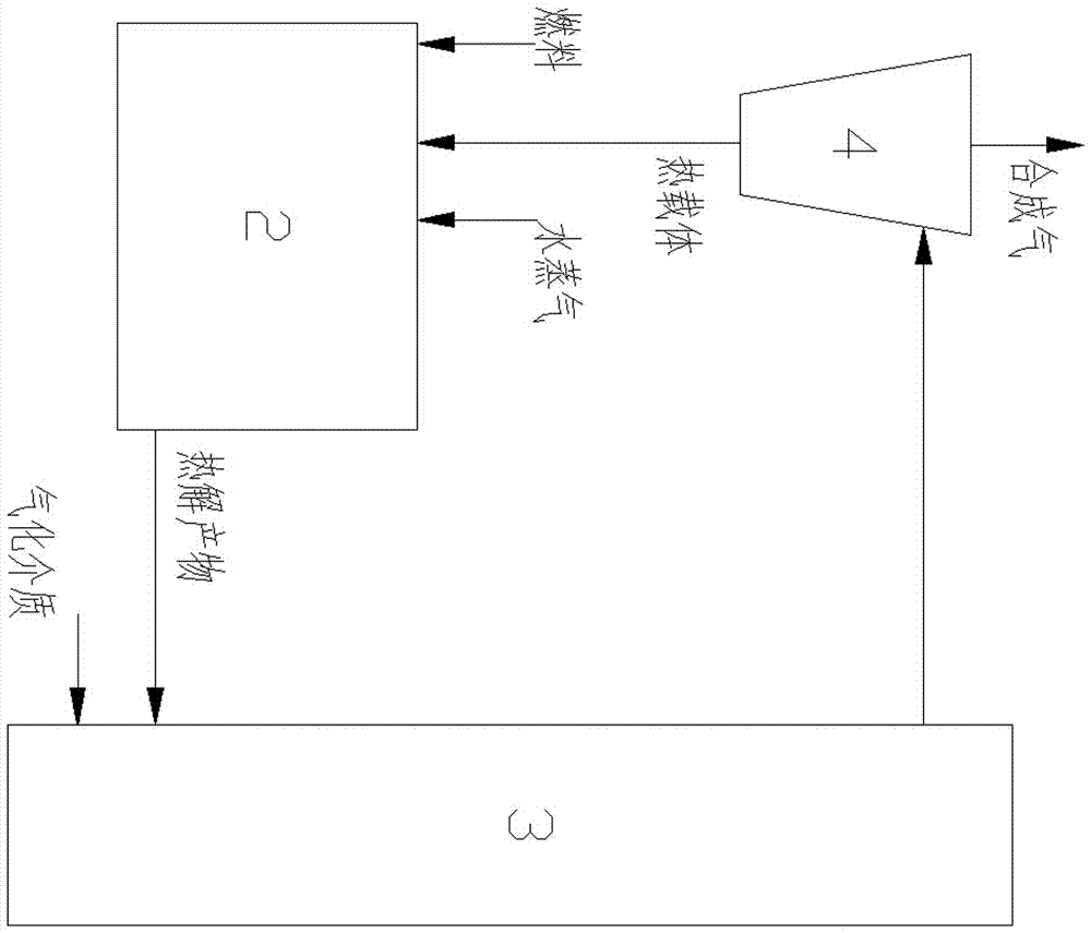
[0033] Specific implementation mode one: as figure 1 , image 3 , Figure 5 As shown, this embodiment discloses a two-stage low-temperature gasification device based on low-order fuel autocatalysis, which consists of a feeding system 1, a moving bed pyrolysis system 2, a fluidized bed gasification system 3 and cyclone separation System 4;

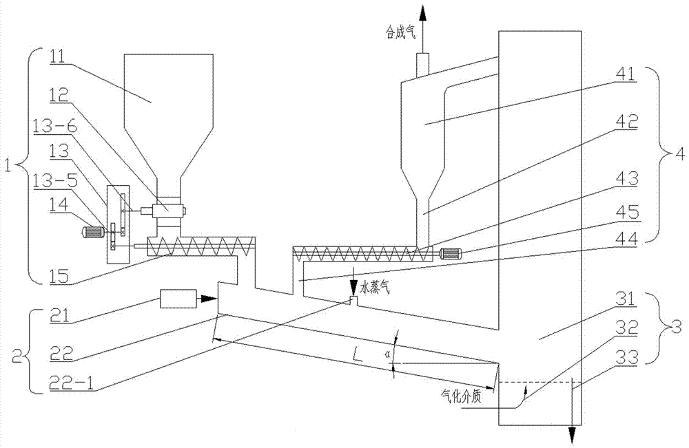
[0034] The feeding system 1 includes a feed bin 11, an air lock 12, a gear box 13, a motor one 14 and a screw feeder 15, and the moving bed pyrolysis system 2 includes an electric vibrator 21 and a pyrolysis reaction 22, the fluidized bed gasification system 3 includes a fluidized bed gasifier 31, an air inlet system 32 and a slag discharge pipe 33, and the cyclone separation system 4 includes a spiral feeder 43, a secondary feeder Pipe 44, at least one cyclone separator 41 and at least one primary return pipe 42;

[0035] The air shutoff device 12 is arranged at the lower part of the silo 11, the power output shaft of the motor one 14 ...

specific Embodiment approach 2

[0042] Specific implementation mode two: as image 3 , Figure 4 As shown, this embodiment is a further limitation of Embodiment 1, the angle between the bottom surface of the pyrolysis reactor 22 and the horizontal plane is α, α=20°~45°. For low-order fuels with different particle mobility, continuous and stable fuel feeding is ensured under low energy consumption of the electrodynamic vibrator 21 .

specific Embodiment approach 3

[0043] Specific implementation mode three: as image 3 , Figure 4 As shown, the present embodiment is a further description of specific embodiment one, assuming that the length of the pyrolysis reactor 22 is L, and the initial position of the length of the pyrolysis reactor 22 is located at the fuel inlet of the pyrolysis reactor 22 At one end, the steam inlet 22-1 is set in the 1 / 3L~1 / 2L area of ​​the pyrolysis reactor 22 in the length direction (for supplementing the moisture required for the gasification and reforming of the pyrolysis product).

[0044] Specific implementation mode four: as image 3 , Figure 4 As shown, this embodiment is a further description of the third specific embodiment. The secondary return pipe 44 is located in the 1 / 3L area of ​​the pyrolysis reactor 22 in the length direction (to ensure that the heat carrier and the low-order sufficient fuel contact and heat transfer).


PUM

PropertyMeasurementUnit
Particle sizeaaaaaaaaaa

Abstract

The invention relates to a two-stage low temperature gasification device based on low-order fuel autocatalysis, and a two-stage low temperature gasification method based on low-order fuel autocatalysis, belonging to the field of clean energy utilization of low-order fuel. A pyrolysis reactor is communicated with a fluidized-bed gasifier and a cyclone separator, and the cyclone separator is sequentially communicated with a primary back feeding pipe, a spiral back feeder, a secondary back feeding pipe and the pyrolysis reactor. A moving bed pyrolysis system is replenished with non-carrier gas, high alkaline metal low-order fuel and alkaline earth metal low-order fuel are pyrolyzed by being heated together with a heat carrier in a mixing way, and part of pyrolysis products are gasified and reformed; the pyrolysis products are directly conveyed into a fluidized-bed gasifying system so as to be subjected to in situ low temperature gasification, and most coke and all tar are involved in the reaction; the heat carrier at an outlet of the fluidized-bed gasifying system is separated from synthesis gas by means of a cyclone separation system, the heat carrier enters to the moving bed pyrolysis system, and the synthesis gas discharged outside. The device and the method which are provided by the invention utilize pyrolysis coke to carry out in situ catalytic pyrolysis on part of tar and utilize reabsorption alkali metal and alkali earth metal to catalyze coke gasification at low temperature, thus realizing high efficient low temperature autocatalytic gasification of the low-order fuel.

Description

technical field [0001] The invention belongs to the field of clean energy utilization of low-order fuels, and in particular relates to a two-stage low-temperature gasification device and method for in-situ catalytic cracking of tar and reabsorbed alkali metals and alkaline earth metals to catalyze coke low-temperature gasification. Background technique [0002] Gasification is one of the main ways to convert carbon-containing fuels and an important technical means to realize their clean and efficient utilization. Low-rank fuels (low-rank coal, biomass, and kitchen waste) have low deterioration, high volatile content, and high gasification activity; low-rank fuels are rich in alkali metals and alkaline earth metals (low-rank coal is rich in sodium, calcium and Magnesium, biomass is rich in potassium, calcium, and magnesium, while kitchen waste mainly contains sodium) has a good catalytic effect on gasification, which can significantly improve the reactivity and carbon convers...

Claims


Application Information

Patent Timeline
IPC IPC(8): C10J3/66C10J3/56C10J3/54C10J3/48C10J3/84
CPCC10J3/48C10J3/54C10J3/56C10J3/66C10J3/84C10J2300/0916C10J2300/093C10J2300/0946C10J2300/0956C10J2300/0959C10J2300/0976C10J2300/1603Y02E20/18
Inventor 许连飞刘辉于鸿胤曹庆喜高继慧吴少华
Owner 哈尔滨丰瀛投资有限公司
Why Eureka
Try Eureka