
Photovoltaic assembly

A technology of photovoltaic modules and laminates, applied in photovoltaic power generation, electrical components, semiconductor devices, etc., can solve the problems of module attenuation, weak resistance to hidden cracks, accidents, etc., achieve reduced thickness or strength requirements, and excellent water vapor barrier performance , reduce thickness and weight effect

Pending Publication Date: 2018-01-19
SUZHOU COOP & INNO GREEN ENERGY TECHNOLOGY CO LTD
View PDF5 Cites 2 Cited by
  • Summary
  • Abstract
  • Description
  • Claims
  • Application Information

AI Technical Summary

Problems solved by technology

[0004] 1. The back of conventional photovoltaic modules is mainly made of composite materials based on PET substrates. In terms of water vapor transmission rate of PET, long-term moisture aging resistance is restricted, and the composite materials on the surface of the rear panel cannot withstand surface wear for a long time ;
[0005] 2. The materials of conventional photovoltaic modules are subject to the RTI (Relative Thermal Index) index in terms of high temperature resistance, generally below 130°C. In practical applications, photovoltaic modules may have local abnormal pollution or block hot spots. Cause the temperature of the photovoltaic module to rise locally to 150°C, resulting in potential local burn damage;
[0006] 3. Conventional photovoltaic modules are subjected to a voltage of about 1000V-1500V when working in a power station. Therefore, the requirements for the withstand voltage of the rear panel surface are high, and there is a risk of leakage if it is partially damaged, leading to the risk of safety accidents;
[0007] 4. Conventional photovoltaic modules are relatively weak in terms of packaging protection for internal cells, such as anti-cracking, and the modules cannot bear local heavy loads. For example, people step on the panel, which will lead to the failure of hidden cracks in the modules;
[0008] 5. Long-term outdoor sunlight and ultraviolet rays are also a relatively high challenge to the rear sheet materials of conventional photovoltaic modules, especially if the internal PET protection is insufficient, yellowing and aging will occur. For this reason, the performance and quality of conventional photovoltaic modules is promised within 25 years , and the commitment to component attenuation is also low, basically at 0.7% per year;
[0009] 6. As the main material of the back panel is plastic, there are obvious defects in fire protection, especially in the application of villa roof components, the potential fire hazard is the risk, and the conventional back panel can only resist C-level fire protection
[0011] 1. Glass is often used on the back of double-glass modules. Due to the relatively heavy glass, the weight of photovoltaic modules increases. Some power stations, especially distributed power stations on the roof, cannot install double-glass modules due to load-bearing problems, which limits the use of double-glass modules;
[0012] 2. Due to the semi-tempered glass on the back of the double-glass module, the edge of the semi-tempered glass is easily broken when the semi-tempered glass is impacted by the outside, resulting in accidents of leakage of photovoltaic modules;
[0013] 3. Due to the use of semi-tempered glass on the back of double-glass modules, the cost of semi-tempered glass is higher than that of conventional modules, which increases the overall cost of photovoltaic modules;
[0015] 5. As a module application, the fire rating has always been the biggest challenge for rooftop photovoltaic applications. In fact, double-glass modules cannot meet repeated tests when facing A-level. The softening point temperature of conventional glass is lower than 700°C. Conventional A-level needs to be It can be maintained at 760±28°C for 10 minutes, and it can withstand the load of the combustion block with a size of 12 inches*12 inches and continue to burn. However, the continuous high temperature glass has actually softened, and it is easy to collapse due to the weight of the combustion block, resulting in test failure. It is also a risk in the application process; while the ordinary back plate is more likely to burn, it is more difficult to keep it at high temperature for a certain period of time

Method used


Image

  • Photovoltaic assembly
  • Photovoltaic assembly
  • Photovoltaic assembly

Examples


Embodiment 1

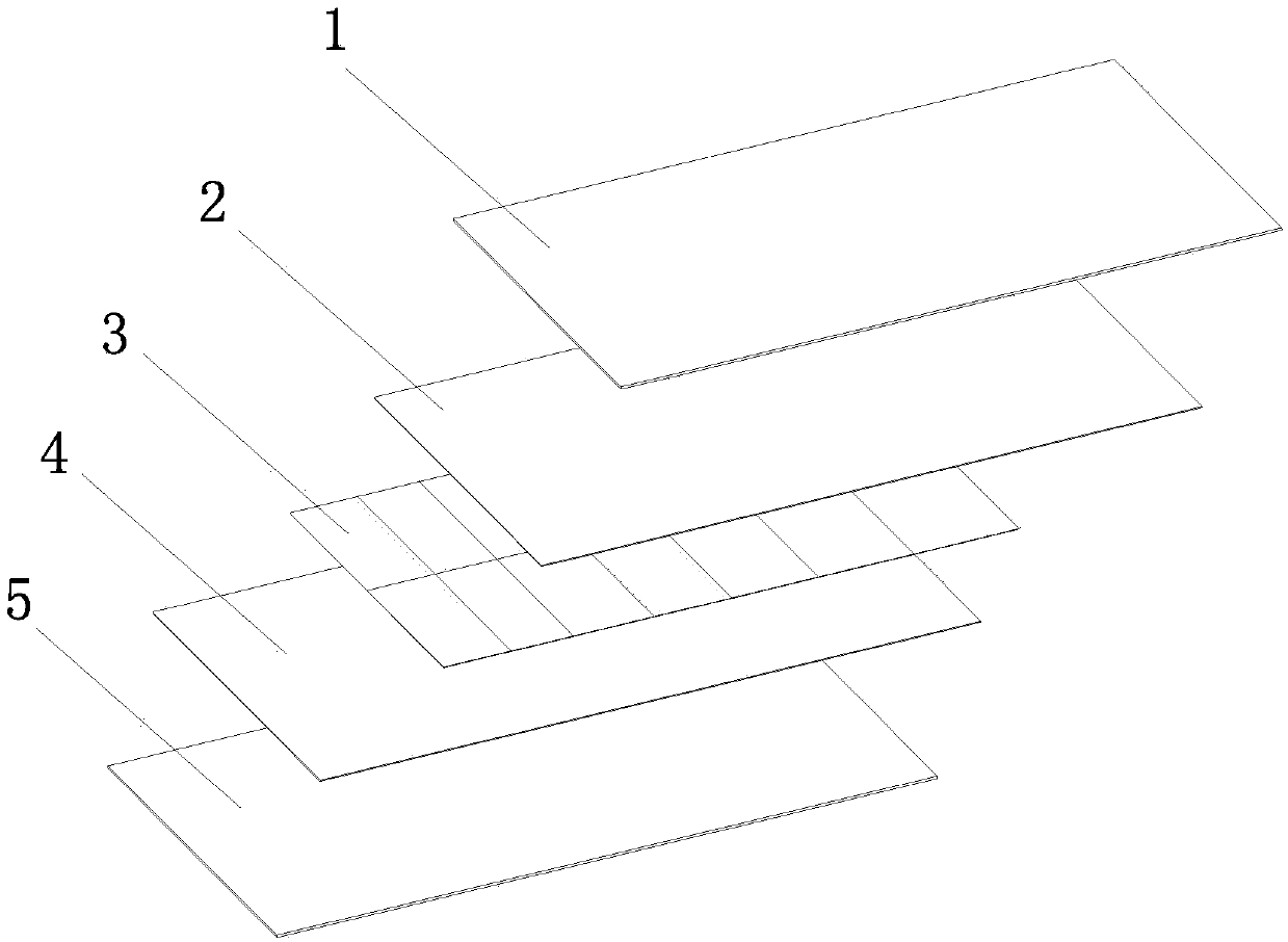
[0046] see figure 1 , a photovoltaic module of this embodiment, comprising a laminate and a frame covering the sides of the laminate, the laminate sequentially includes a front plate 1, a front packaging material 2, a battery layer 3, and a rear packaging material from top to bottom 4 and a back plate 5, the back plate 5 is a metal plate or an inorganic material plate.

[0047] Metal plate 5 can be iron plate, steel plate or aluminum plate. The surface of the metal plate 5 is coated with insulating varnish and / or color paint. The thickness of the metal plate 5 is 0.1-0.5mm, which is much thinner than that of conventional 2.5mm or 2.0mm glass.

[0048] In this embodiment, the rear plate is a metal plate 5 and is a steel plate 5 . Although the packaging material is an insulating material, which can play a certain insulating role, the packaging material will be squeezed during the lamination process of the laminate, causing the battery layer 3 to still be in contact with the m...

Embodiment 2

[0053] A photovoltaic module in this implementation is basically the same as the first embodiment, the difference is that the steel plate 5 in this embodiment is not only coated with insulating varnish, but also coated with colored paint, and the color of the paint can be selected according to the requirements of customers , so that it is both beautiful and can form a protection for the metal plate, thereby increasing the service life of the photovoltaic module.

Embodiment 3

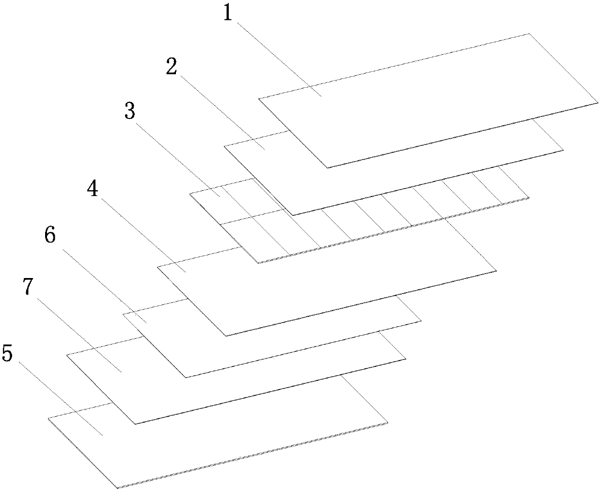
[0055] see figure 2 , a photovoltaic module in this implementation is basically the same as the first embodiment, the difference is that the insulation treatment between the metal plate 5 and the battery layer 3 in this embodiment is that the side of the metal plate 5 close to the battery layer 3 has an insulating layer 6 In order to achieve better insulation effect. The insulating layer 6 is made of PET, glass fiber board, soft ceramic, flexible stone or asbestos board.

[0056] There is an adhesive layer between the insulating layer 6 and the metal plate 5 . The material of the adhesive layer is a conventional packaging material such as EVA, POE, PVB, and the like. Among them, EVA is ethylene-vinyl acetate copolymer, POE is polyolefin elastomer, and PVB is polyvinyl butyral.

[0057] In this embodiment, the surface anti-corrosion treatment is also carried out on the metal plate 5 to achieve a longer service life. erosion.


PUM

PropertyMeasurementUnit
Thicknessaaaaaaaaaa

Abstract

The invention discloses a photovoltaic assembly, which comprises a laminated part and a frame which wraps the side edge of the laminated part. The laminated part successively comprises a front plate,a front packaging material, a battery layer, a rear packaging material and a rear plate from top to bottom. The rear plate is a metal plate which is subjected to insulation treatment. The photovoltaicassembly adopts the rear plate made of metal materials, so that the thickness and the weight of the photovoltaic assembly can be further reduced. The water vapor blocking property of the metal materials is excellent, so that the decomposition problem of the packaging materials due to the water permeability can be further effectively avoided. The thermal conductivity of the metal materials is relatively good, so that the heat generated during the power generation of the photovoltaic assembly can be dissipated into the air at the most fast speed by adopting the metal materials. The power generation efficiency of the photovoltaic assembly is improved. The rigidity of the metal materials of the rear plate is utilized, and the front plate of the photovoltaic assembly can reduce thickness or strength requirements. The overall weight of the photovoltaic assembly is reduced. The photovoltaic assembly is low in weight and high in performance. The overall cost of the photovoltaic assembly is reduced, and the method has a good application and popularization prospect.

Description

technical field [0001] The invention relates to the technical field of photovoltaic module installation, in particular to a photovoltaic module. Background technique [0002] With the continuous consumption of energy and the rise of energy prices, the development and utilization of new energy has become the main topic of research in the field of energy. Because solar energy has the advantages of no pollution, no regional restrictions, and inexhaustible supply, the study of solar power generation has become one of the popular directions for developing new energy sources. At this stage, using solar cells to generate electricity is a major way for people to use solar energy. [0003] With the improvement of the safety performance requirements of photovoltaic modules, the shortcomings of conventional photovoltaic modules are becoming more and more obvious. At present, the main shortcomings of conventional photovoltaic modules include: [0004] 1. The back of conventional photo...

Claims


Application Information

Patent Timeline
IPC IPC(8): H01L31/048H01L31/049
CPCY02E10/50
Inventor 张雨军陶爱兵唐洪张欢欢沈佳
Owner SUZHOU COOP & INNO GREEN ENERGY TECHNOLOGY CO LTD
Learn More