

Thermotropic delayed fluorescence material
A thermally induced delayed fluorescence, C6-C60 technology, applied in luminescent materials, electrical components, circuits, etc., can solve problems such as poor thermal stability and low glass transition temperature
- Summary
- Abstract
- Description
- Claims
- Application Information
AI Technical Summary
Problems solved by technology
Method used
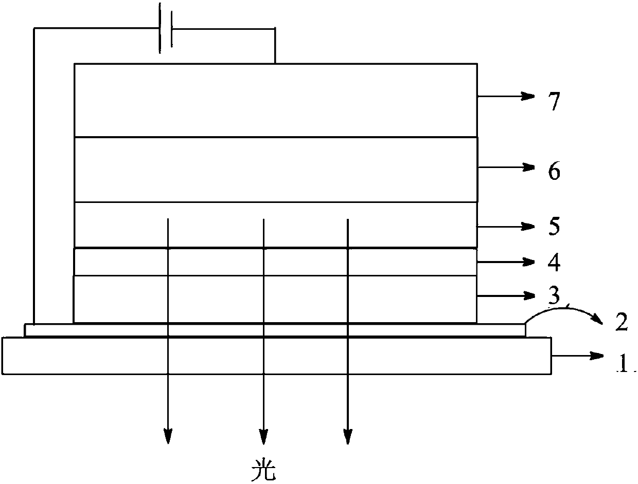
Image

Examples
Embodiment 1
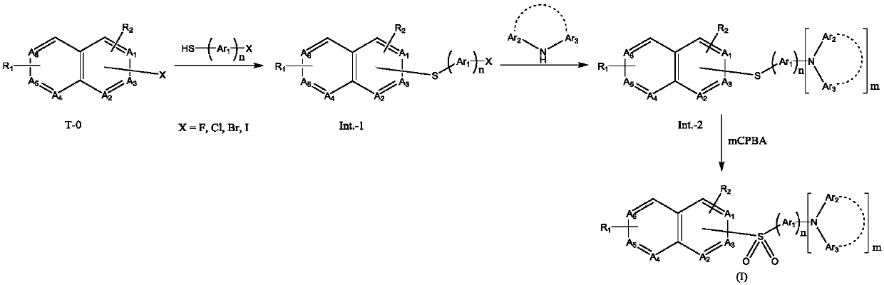
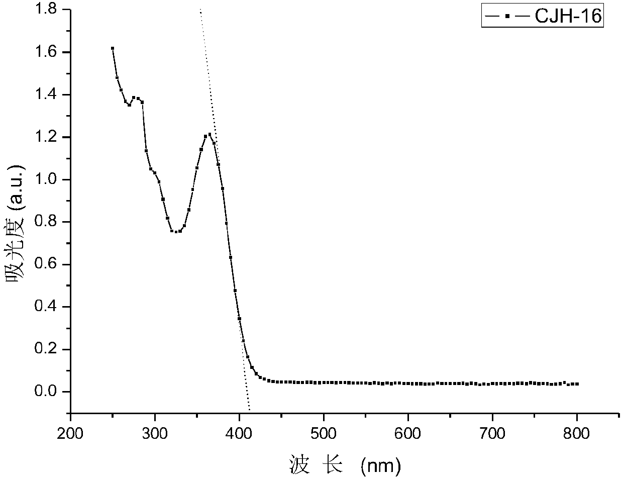
[0072] A thermally induced delayed fluorescent material, namely compound CJH-16, its structural formula is as follows:
[0073]
[0074] The preparation method of above-mentioned compound CJH-16, comprises the steps:
[0075] The first step: the preparation of intermediate T-1
[0076]
[0077] 10.0g (61mmol) of 2-chloroquinoline and 11.6g (61mmol) of 4-bromothiophenol were mixed, added 200ml of water, heated and refluxed and stirred for 14 hours, cooled to room temperature, filtered, the filter cake was washed with water, and the silica gel column After separation and purification, 17.8 g of yellow solid was obtained with a yield of 92%.
[0078] The second step: the preparation of intermediate T-2
[0079]
[0080] 5g (15.8mmol) of intermediate T-1, 6.45g (17.3mmol) of intermediate T-11, 6.7g (63.2mmol) of anhydrous sodium carbonate are mixed, then add 365mg (0.316mmol) of Pd (PPh 3 ) 4 Catalyst, then add 20mL of toluene, 10mL of ethanol and 10mL of water, stir ...
Embodiment 2
[0085] A thermally induced delayed fluorescent material, namely compound CJH-42, its structural formula is as follows:
[0086]
[0087] The preparation method of above-mentioned compound CJH-42, comprises the steps:
[0088] The first step: the preparation of intermediate T-3
[0089]
[0090] 10g (41.5mmol) of 2-chloro-4-phenylquinazoline and 7.85g (41.5mmol) of 4-bromothiophenol were mixed, and intermediate T-3 was prepared according to the operation method of the first step of Example 1 , to obtain 14.7g yellow solid, yield 90%.
[0091] The second step: the preparation of intermediate T-4
[0092]
[0093] Mix 5g (23.9mmol) of 9,9-dimethylacridine and 7.4g (26.3mmol) of 4-bromoiodobenzene, add 457mg (2.4mmol) of cuprous iodide, then add 50ml of NMP, and stir Raise the temperature at 120°C for 12 hours, cool to room temperature, filter, pour the filtrate into 500ml of water, filter, wash the filter cake with water to obtain a white solid, and recrystallize with e...
Embodiment 3
[0104] A thermally induced delayed fluorescent material, namely the compound formula CJH-50, its structural formula is as follows:
[0105]
[0106] The preparation method of above-mentioned compound CJH-50, comprises the steps:
[0107] The first step: the preparation of intermediate T-7
[0108]
[0109] Mix 10g (31.6mmol) of T-1 and 100ml of glacial acetic acid, add 1ml of concentrated sulfuric acid, add 5.6g (35.0mmol) of bromine, raise the temperature to 100°C and stir for 12 hours until the red color disappears, cool to room temperature, reduce Concentrate under reduced pressure to remove glacial acetic acid, add 200 ml of ice water to the residue, extract with dichloromethane, combine the organic phases, and concentrate to dryness under reduced pressure to obtain 10 g of yellow oil with a yield of 83%.
[0110] The second step: the preparation of intermediate T-8
[0111]
[0112] 10g (25.3mmol) of T-7, 9.3g (55.6mmol) of carbazole, and 10.5g (75.9mmol) of an...
PUM
| Property | Measurement | Unit |
|---|---|---|
| thickness | aaaaa | aaaaa |
| thickness | aaaaa | aaaaa |
| thickness | aaaaa | aaaaa |
Abstract
Description
Claims
Application Information