Energy recycling type temperature adjusting dehumidification sludge drying machine system

An energy recovery and sludge drying technology, applied in sludge treatment, water/sludge/sewage treatment, dehydration/drying/concentrated sludge treatment, etc., which can solve the problem of high energy consumption, safety risks, and working environment of drying workshop Poor and other problems, to achieve the effect of less wearing parts, long service life, and inhibiting the volatilization of volatile gases

Pending Publication Date: 2018-04-06
BRIGHT AIR CONDITIONING
View PDF4 Cites 9 Cited by
  • Summary
  • Abstract
  • Description
  • Claims
  • Application Information

AI Technical Summary

Problems solved by technology

[0003] The existing sludge dryer has the following problems: (1) High energy consumption: sludge drying is a process of net energy consumption, and traditional sludge drying equipment adopts heating, drying and dehumidification methods, and the energy utilization rate is low
(2) There are safety risks. Nitrogen is usually added to reduce the oxygen content in sludge drying to avoid explosions; (3) It is not environmentally friendly: a large amount of odor is emitted, and an exhaust gas treatment system needs to be built; the working environment of the drying w

Method used


Image

  • Energy recycling type temperature adjusting dehumidification sludge drying machine system
  • Energy recycling type temperature adjusting dehumidification sludge drying machine system
  • Energy recycling type temperature adjusting dehumidification sludge drying machine system

Examples


Embodiment

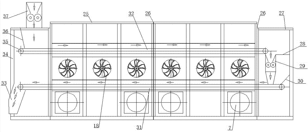
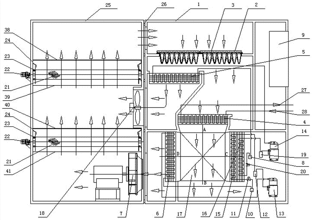
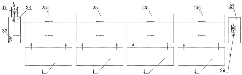
[0043] Such as figure 1 with figure 2 The shown works as follows:

[0044] 1. Material flow:

[0045] Sludge feed→Sludge feed strip cutter 37→First layer of mesh belt 32→Sludge strip crushing device 29→Second layer of mesh belt→Outlet (conveyor inlet).

[0046] 2. Cyclic drying process

[0047] 2.1 Circulating drying channel A: drying box 25 (air outlet) → plate filter 2 → bag filter 3 → No. 2 condenser 5 → circulating fan 18 → drying box air mixing space → air uniform plate → first layer of net Belt 32 → uniform air plate → drying box 25 (air outlet).

[0048] 2.2 Cycling dehumidification and drying channel B: drying box 25 (air outlet) → plate filter 2 → bag filter 3 → temperature-adjusting cooler 4 → heat recovery device 17 → No. 2 evaporator 16 → No. 1 evaporator 15 → Heat recovery device 17→No.1 condenser 6→Centrifugal fan without volute 7→Second layer air equalizing mesh belt 31→Air equalizing plate→Drying box air mixing space→Air equalizing plate→First layer mes...


PUM


Abstract

The invention discloses an energy recycling type temperature adjusting dehumidification sludge drying machine system. A sludge feeding bar cutting device is arranged at the top of an inlet/outlet transmission tank; sludge is extruded into a porous plate by using the sludge feeding bar cutting device through a rotating cutter; net strips are arranged inside a drying tank; a cut bar feeding device is arranged at one end of the net strip; a temperature adjusting dehumidification drying device is arranged on one side of the drying tank; the temperature adjusting dehumidification drying device is connected with the bottom of the drying tank through an air supply hole; the net strips are divided into two layers; the first layer of the net strips and the second layer of the net strips are arranged from top to bottom; the start end of the second layer of the net strips is arranged at the lower part of the tail end of the first layer of the net strips; materials of the first layer of the net strips drop into a crushing device at the tail end of first layer of the net strips; crushed sludge drops onto the start end of the second layer of the net strip and finally drops into a discharge hole.By adopting the system, sludge of which the water content rate is within 80-65% can be effectively treated, sludge bar extrusion is not affected, flexible adjustment is achieved, the supply amount can be adjusted through variable frequency of a screw rod pump, a good and uniform spreading effect is achieved, the air permeability of sludge bars can be adjusted, and the requirements of different types of sludge bar extrusion can be met.

Description

technical field [0001] The patent of the present invention relates to the field of drying equipment, specifically an energy recovery type temperature-regulating dehumidification sludge dryer system. Background technique [0002] At present, the commonly used drying systems are mainly direct drying drum drying process, multi-layer step drying process, rotary disc drying process, and fluidized bed drying process. However, sludge belt drying has attracted widespread attention due to its strong adaptability to wet sludge, fewer maintenance parts, long service life, and low drying temperature, and has a good market application prospect; dehumidification combined with mesh belt drying sludge drying Sludge belt drying technology is a new trend, which has great advantages in terms of energy saving and environmental protection. Sludge dehumidification and drying technology will dominate sludge belt drying. [0003] The existing sludge dryers have the following problems: (1) High ene...

Claims


Application Information

Patent Timeline
IPC IPC(8): C02F11/12C02F11/00B02C21/00B02C18/14
CPCC02F11/00C02F11/12B02C18/142B02C21/00C02F2303/06
Inventor 高士清郭秀丽高建华郭小明李传庆李栋
Owner BRIGHT AIR CONDITIONING
Why Eureka
Try Eureka